Quite some time has passed since my last real posts, and looking at the car it feels like not much has happened, but re-reading the blog i realized quite a lot did.
No, the massive motor, differential and chain-drive is not in place yet and as you could see in my last blog one of the old gearboxes died. I also mentioned i wanted to keep it rolling during the weekends when my little guy was here, so tearing it all down and start building the drive-chain on the car itself was a no-go for me.
The cat ate the led-lights
And what’s left of it was pulled away by my soon to be 2 years old little rebel :) They will be replaced with more rugged LED strips for actual cars to make sure they get to stay.
I made a few poor attempts to patch the old gearboxes, but ended up removing it all together while awaiting the somewhat beefier replacement 550’s.
These are the RS-550 12VDC doing 23.000 rpm.
The search for wheels end
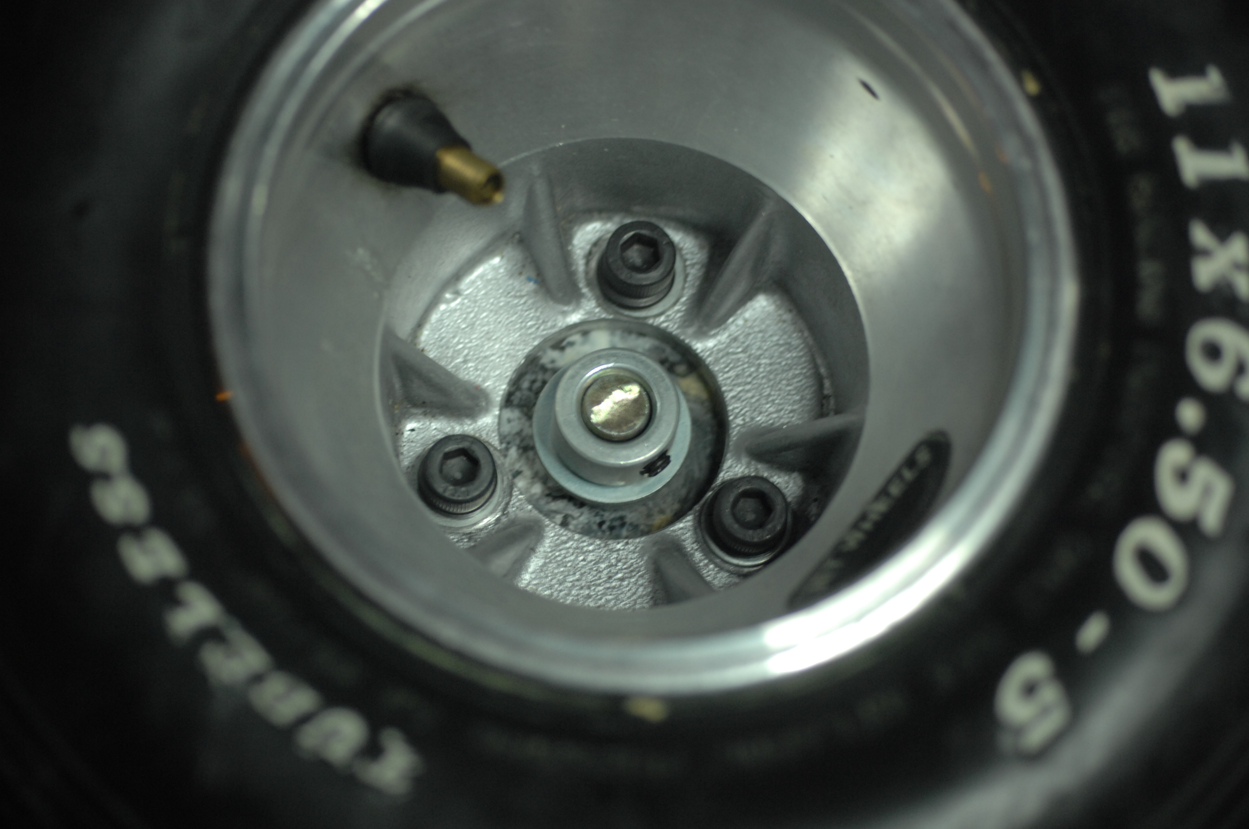
Wheels was an issue, and yes, i went the expensive way with a set of used DeCont gocart tyres.
Front: LeCont 10×4.50-5.
Rear: LeCont 11×6.50-5.
I ended up paying around 160 euros for the set. It looks pretty fancy, i must say and my son loves them.
There is no object so soft but it makes a hub for the wheeled universe. Walt Whitman
I now had wheels but no hubs for the rims to go on and while browsing ebay i didn’t find anything that was reasonably cheap or would just take too long to ship.
Being a responsible adult as i am, i have saved all scrap PLA from failed 3dprints, recycling this makes great sense. I decided to mold them so i measuring the inner diameter of the rim, then ran off to the local food-store and bought two canisters of corn that had just about the same diameter. The cans were emptied, cleaned and put on a the stow in a pan, heated to 210 degrees and the plastic was slowly added to make sure no large bubbles formed.
These chunks were milled flat to size. I drilled and tapped M8 holes and secured the wheel.
Art consists of limitation. The most beautiful part of every picture is the frame. Gilbert K Chesterton
I also started building the frame that once finished will replace much of the under-carriage of the current car. The game-plan is simple. Build a rolling frame with suspension, brakes, gears, differential, steering and motor and once ready transplant that frame to the car. Until now i started created 3 revisions of the back-end but stopped half way and reflected over decisions, scrapped it and started over again. This is most likely nothing what it will look like when “done”.
I have used aluminium as much as possible to keep the weight down. I got my hands on a 1300x60x40mm u-profile that shapes the base of the frame. The barrings housing holding the differential had to be milled down slightly, and 10x15mm strips add supports.
Initially flaky lower control arms moved me from cheap hollow tube, to solid square stock, to end up with 10mm thick aluminum blocks at the end.
I have been able to do most of the milling on my tiny Proxxon MF70 Micro-mill, but i REALLY need a bigger machine that eats more material, preferably CNC but for now this will have to do.
Rear differential, bearings, chain, chain-tentioner, electric motor and the lower control arm mounted. Battery box will be mounted on the opposite side to the motor to balance out the weight.
All of this will be covered under the driver seat to avoid anyone losing a tiny finger. I am considering to add linear actuators to the suspension to be able to raise and lower it as i think it would make it look sleeker. Not sure yet, leave your comments.
The child supplies the power but the parents have to do the steering. Benjamin Spock
I bought a gokart front steering kit, including wheel-hubs. I welded a few nuts and bolts to them allowing the pocket-bike disc-brakes and calipers to be mounted, then gave them a splash of paint.
Life is made of ever so many partings welded together. Charles Dickens
I ended up buying a dirt-cheap 200 amp MMA/TIG. I burned a few boxes of rods and i am starting to get the feel of it. And yes, I even welded aluminium, but like everyone said, it’s hard to do with stick (however not impossible).
So far this project is moving a lot slower than i am wished for but it’s busy days and i have spent a fair amount of time picking up milling, using lathe and welding. With this mix of new trades i am reconsidering a lot of decisions made prior to posting here, so you have not seen half of it.
Anyway, just wanted to let you know i was making some progress.
Just an update on parts, don’t get all excited yet :)
I have been sick as a dog the last 2 weeks back and forward, hit by 2 strains of flu that kept me in bed or begging to the porcelain god for most of the time, so not much has happen except the siren feature during the last days of being well, which is appended to part one of this series, if you missed it.
Beside that landing on the first page of HackerNews drove a lot interest, comments and feedback which i’ve only been partially able to respond to or look into to, will follow up. Just like the prior post, i will keep editing it as the build progresses and stuff i’ve done might become redundant, or included. In the meantime parts have kept arriving and i’ve felt well enough to take some pictures and blog a little so for now this post is mainly about the collection of parts.
Mechanics
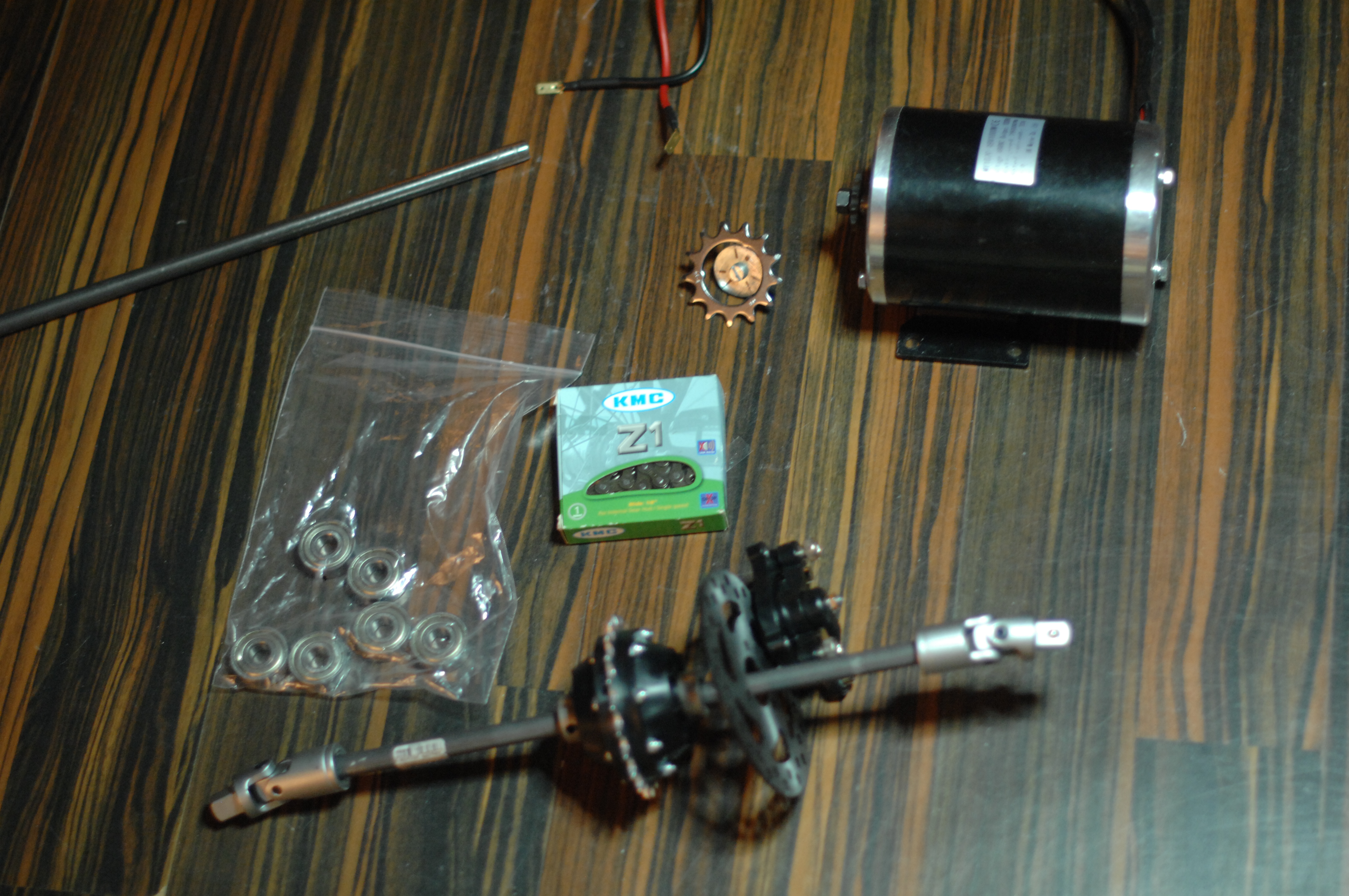
So. Motor, rear diff, axles, disc-brakes, chains, sprockets have arrived:
Motor:
MY1020 48V1000W 2800RPM at a rated current of 32Amp. I giggled a little while placing this order. This engine is a beast, but with that said i am running it on 12 volt on a very fine-grained ESC and controller. Following days i will figure out a nice way to measure the rpm’s i am getting out of it and make sure i gear it correctly. My aim is strength, not speed.
Differential:
General transmissions gt82005 Differential d16 This thing is beautiful, and the folks at General Transmissions are great. I had few questions, which was answered immediately, and shipment took 2 days from Germany.
Chain and sprocket:
Standard bicycle chain and sprocket, from the bike-store around the corner. As i am still not sure what kind of rpm i get out of the engine, i reserve to detail more before i know it will fit the bill.
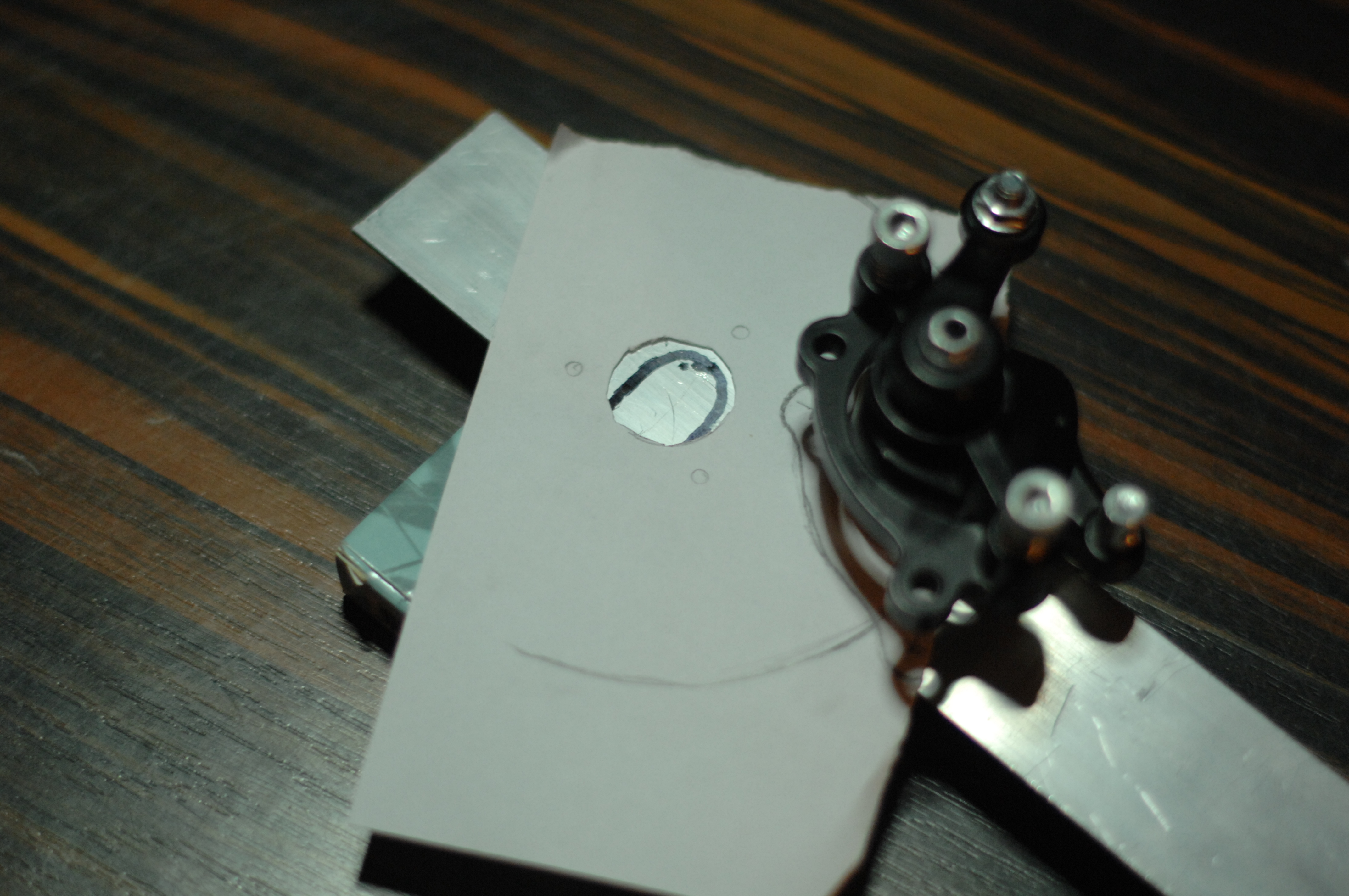
Brakes:
I was looking for brakes for a while, looking mostly at disc-brakes for bicycles but these are not cheap and not the smallest either. Turns out pocket-bikes have mechanical brakes that could work for me. I ordered these brake-claws and these 120 mm discs. However to pull these brakes i also needed some heavy duty servos.
My creative process:
Not sure what other people do this process, but i tend place things on the floor, make a temporary placeholder or frame from anything i have around (cardboard, paper-molds, pvc plastics) for the parts i need, make measurements to make sure it will fit and at the point i am relatively sure the puzzle will go together with no issues, this is when i start raw cutting materials. Lastly the modifications is done to the car. This is just to make sure my son has his car during the weekends he spends with me, allowing me to keep progressing in the background. You will see this reflected in how i structure what gets done when.
Why not use CAD like normal persons?
Good question, i do realize the benefits of modern tools. I do model in Blend3r for 3d-printing, but am also trying to get into FreeCAD for these kind of jobs. It will come, i am not afraid of technology :)
In the meantime in Amish-land:
Measurement for the front disc brake holder is being made.
TIL: Not all aluminium is weldable
As my welding rig is slowly getting ready, my power supply is up to standard and i’m mentally ready to take on a new challenge i started reading up on welding processes with aluminium. Most people advise against welding aluminium because it’s notoriously hard. It turns out the challenge is that aluminium melts around 660 degree’s Celsius, while the slag forming on the weld has a considerably higher melting temperature. To avoid oxidation it seems the key is using AC, where one polarity melts the metal and a switch of polarities causes the weld to clean itself.
From the little i’we seen and read so far, most people who advise from welding this material, come from welding steel and try to apply their steel-welding skills to this alloy, and that shit does not fly well.
It also seems that depending on the grade of aluminium (i.e depending if it’s a alloy mixed with elements such as magnesium, silicon, manganese, tin or copper) will make it more or less weldable. There are 8 main series (1xxx,2xxx, and so on called Wrought alloys) that all have very different properties in terms of strength, weldability, welder settings and filler materials added while welding. I would be lying if i said this will not take a while to get my head wrapped around.
Problem now is that all the material i bought have been purchased at general warehouses, so asking their staff what grade of aluminium they are selling and what alloys it’s composed of would be as useful as asking a toddler about bending time space continuum. I might actually be better of going to a proper metal supplier and be sure i know what i am buying. This is a bit of a setback, but that’s what you get for shopping first and asking questions later.
At the moment i understand i should avoid 2xxx and 7xxx (with a handful of exceptions) as these are considered unweldable (please correct me if i am wrong).
As for fillers, different grades have corresponding filler materials that will give the best results.
Having read this i understand that if you come from welding MIG, TIG or MMA on carbon steel or stainless, to slabbing two unknown pieces of aluminium together, the learning curb gets steep very fast. Lucky for me, i never welded more than a little MIG when i was a kid, so it’s all new. Not sure how or if that will benefit me, but we will see.
For now it seems my first welding will be a little stainless steel stick welding to get the sprocket on an axle. This seems like a reasonable challenge until i know what the hell i am doing :)
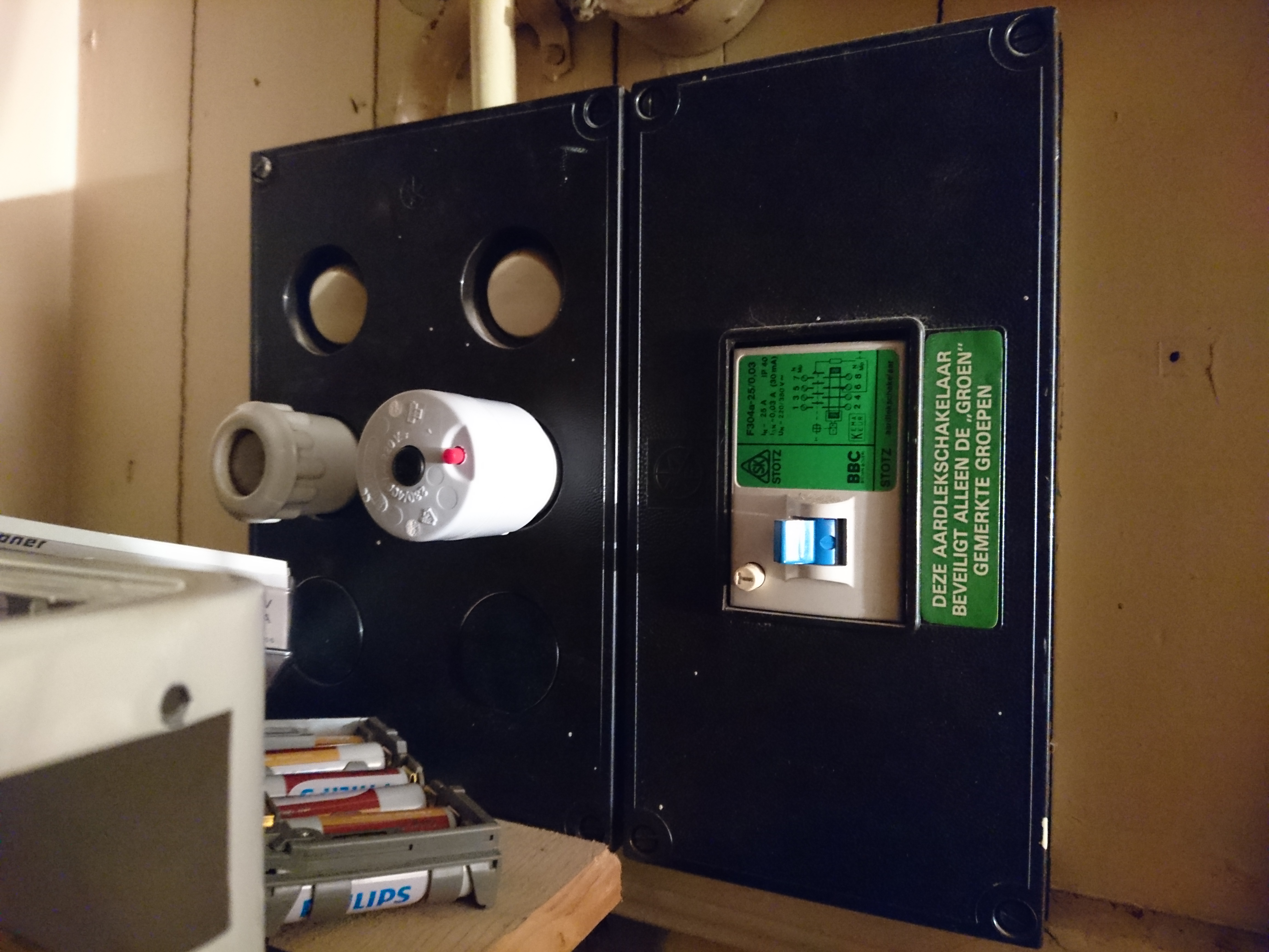
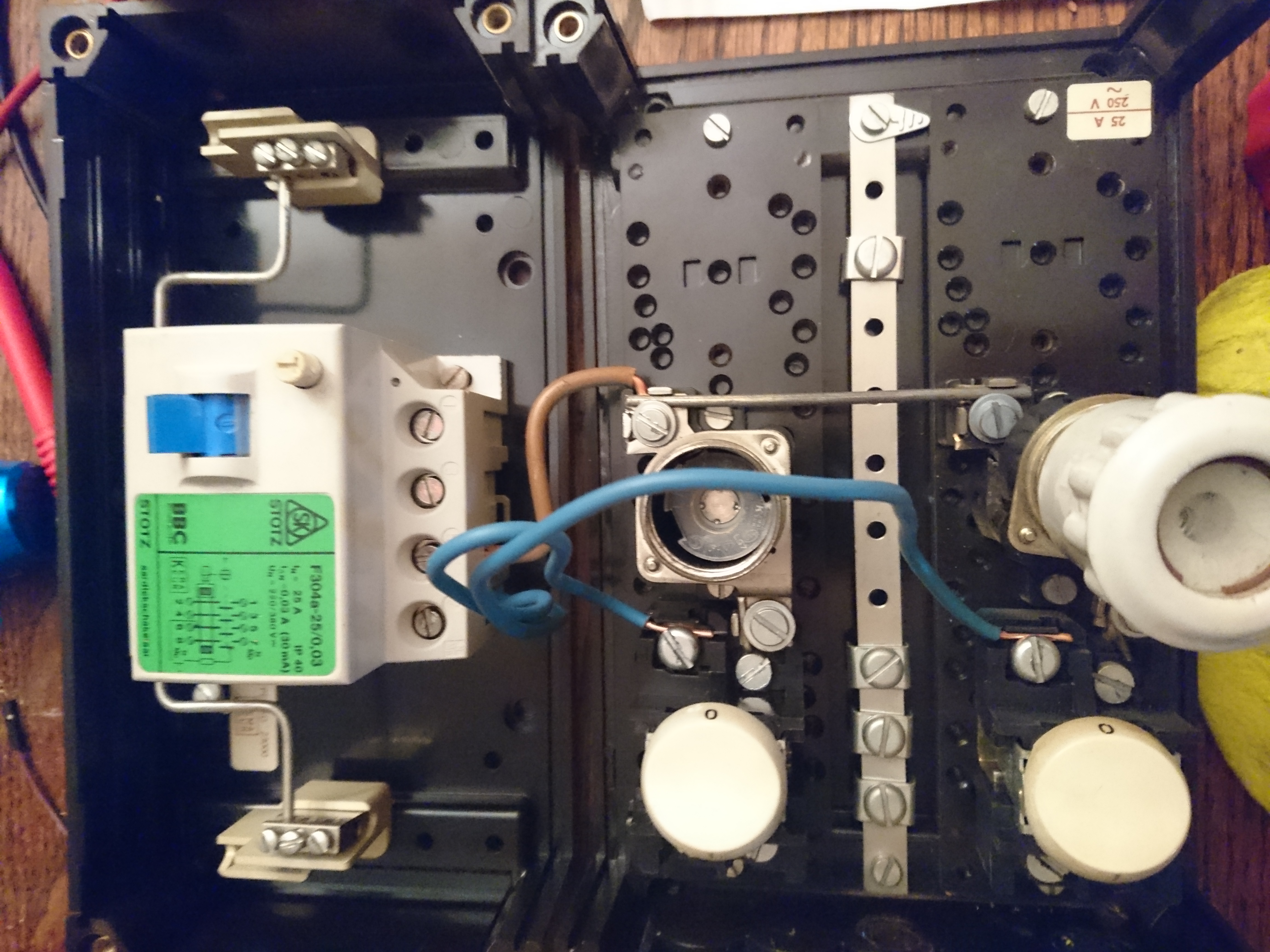
I bought my house in 2006, and beside for being an old drafty house that applies to standards set in the 50’ies i love the place.
However at an early stage i could see flickering in the light and hear arching electricity at some point. I did intend to address it and managed to narrow it down to the fuse-box but due to life changing rapidly in all directions i never got around to it.
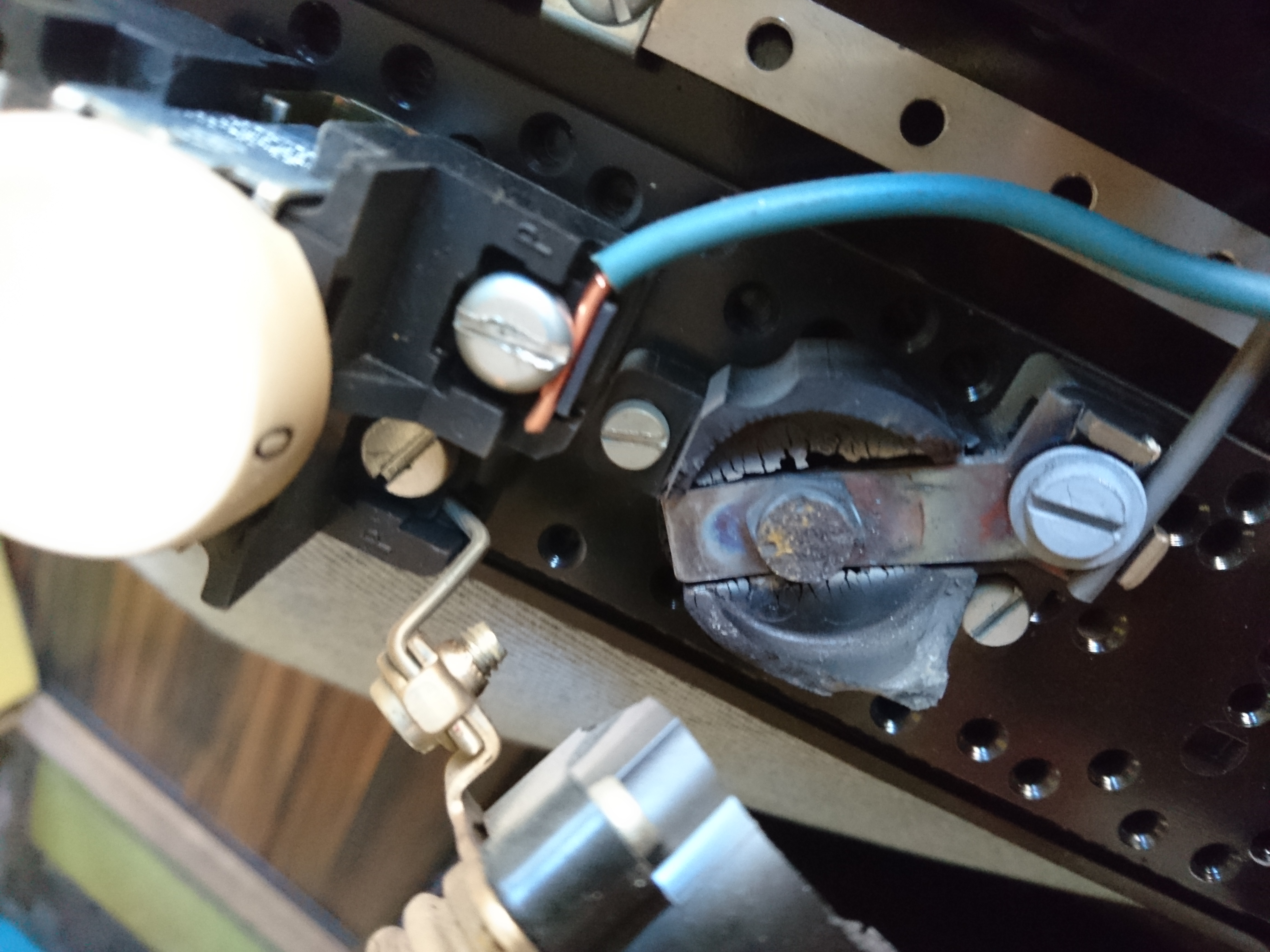
At some point a fuse burned out, and as was replacing it i almost burned myself on the fuse-stand. I shut down the main-power, removed the fuse and only to notice the top of the porcelain fuse all burned out. With the power shut down, i used a screwdriver with some sandpaper on the top to clean up the metal to once more have contact. In the process i found another top of the fuse melted into the fuse-stand. I spent 20 minutes making it shine again, and since that it just worked. However, as i started rebuilding the car of my son i realized this would not be safe to run a welding machine consuming 5-8kw.
It turns out one of the fuse holders had broken, probably due to heat and that the fuse had been arching ever since. I don’t think you will ever get closer to an electric fire, without actually having a fire.
At a closer look i noticed something even worse. My apartment only has one phase coming in, but my fusebox used a 3 phase ground-breaker, which means that in order for it to break the power, all phases would have to be short-circuited which could never happen with a single phase. This means the ground-breaker might as well have been a nail or piece of cable, as it would never brake if something went wrong.
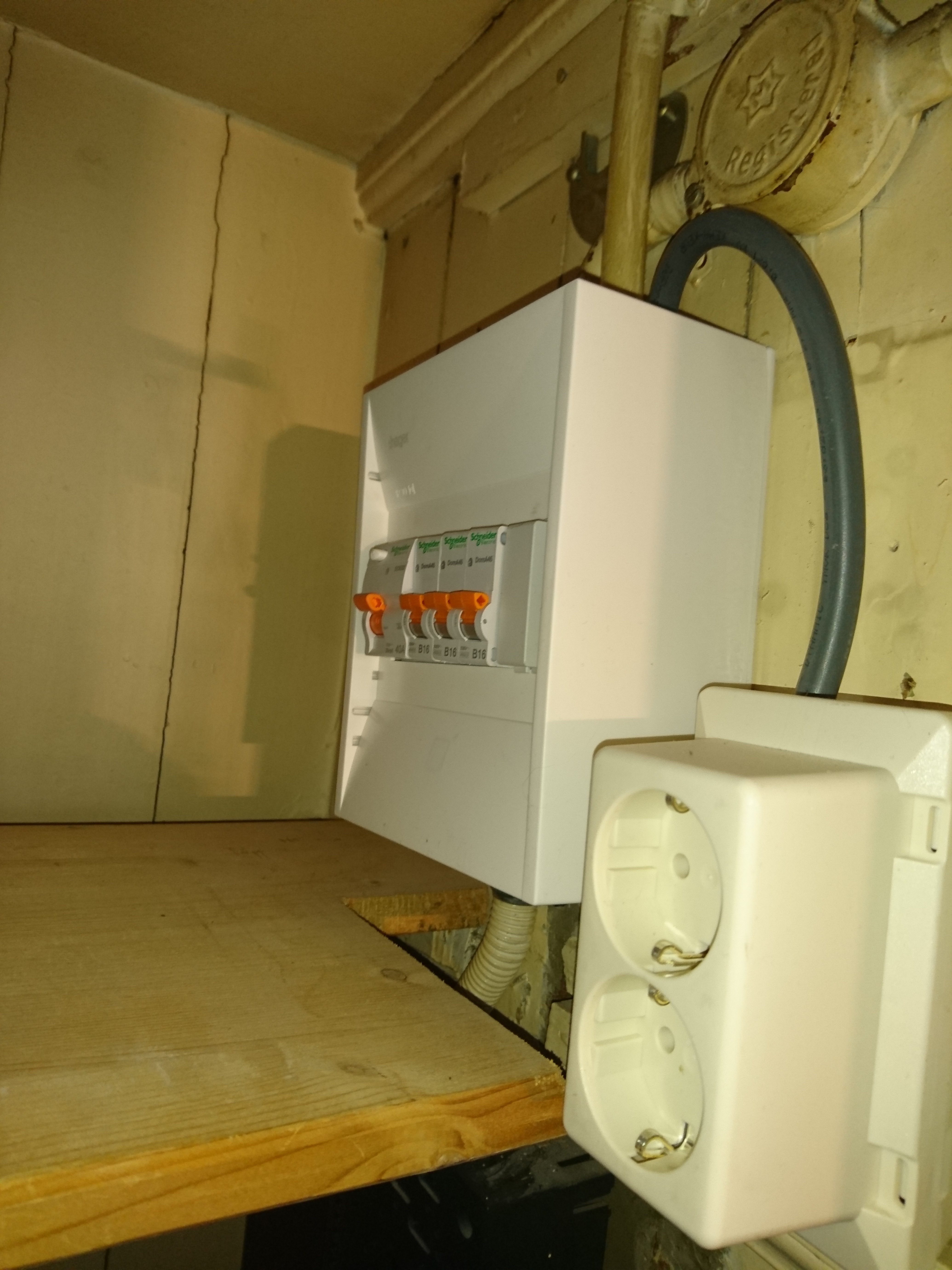
Even prior to knowing this, i didn’t trust the wiring in the walls to be up to standard, and after seeing it, it made sense not to. I therefore added a new phase, with proper cable to it’s own power-socket next to the fusebox. I will trust only this socket for anything which uses a lot of juice.
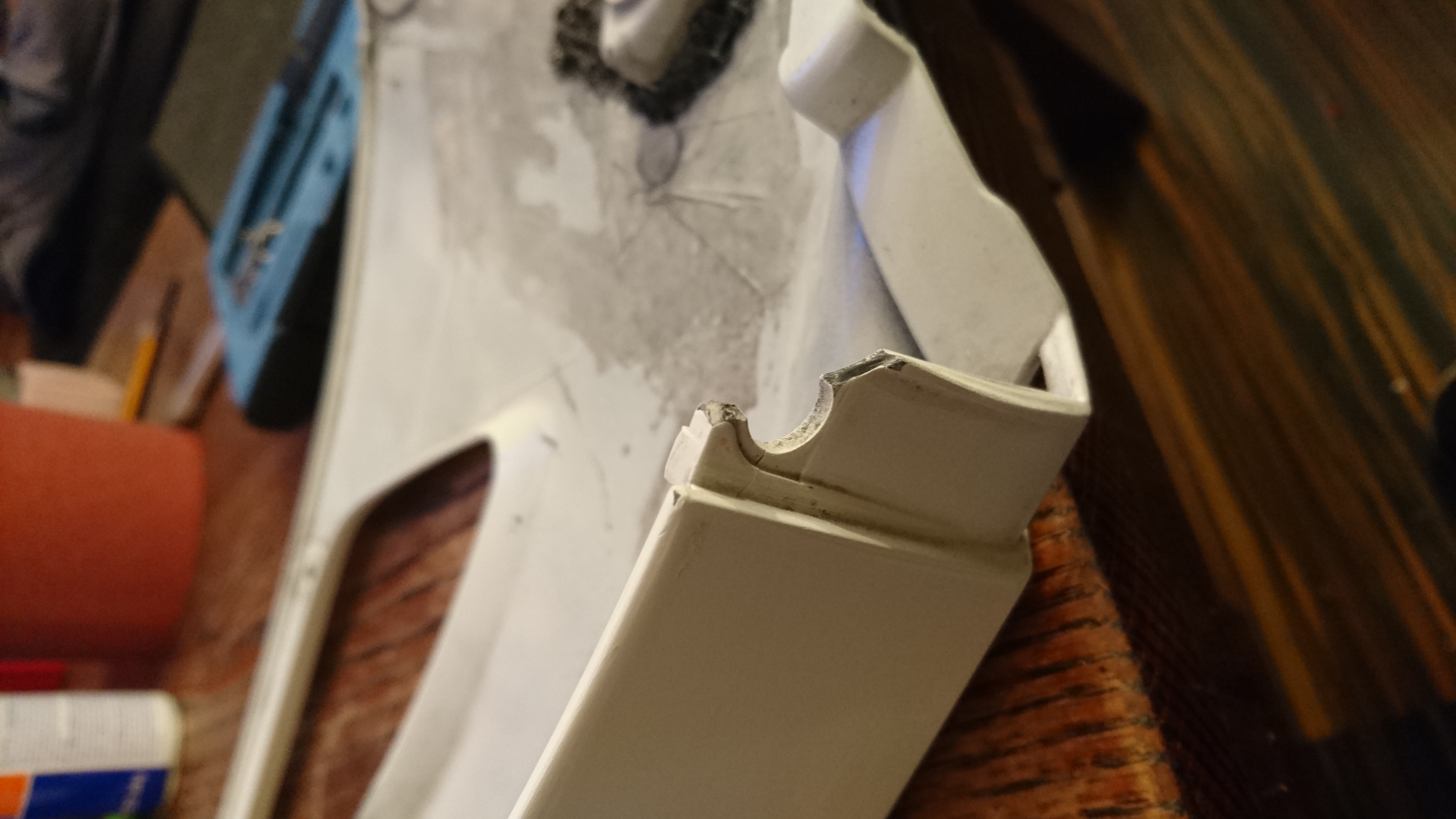
Having crashed my bike a few times my fairing have had better days. I read up and realize it could be welded using a regular solder-iron.
The plastic i use for this are ABS-rods specifically made for ABS-welding, but if you have ABS filament for 3d printing, this will work as well.
The technique used is simple. Heat the area where you want to add material with a soldering iron and insert new material slowly building it up again. You can use a gas driven soldering iron, but only if it has a tip. Exposing ABS to a torch flame will ruin it in a heart-beat.
Start by cleaning up the piece, filing down dirt to expose clean material.
Cracked piece
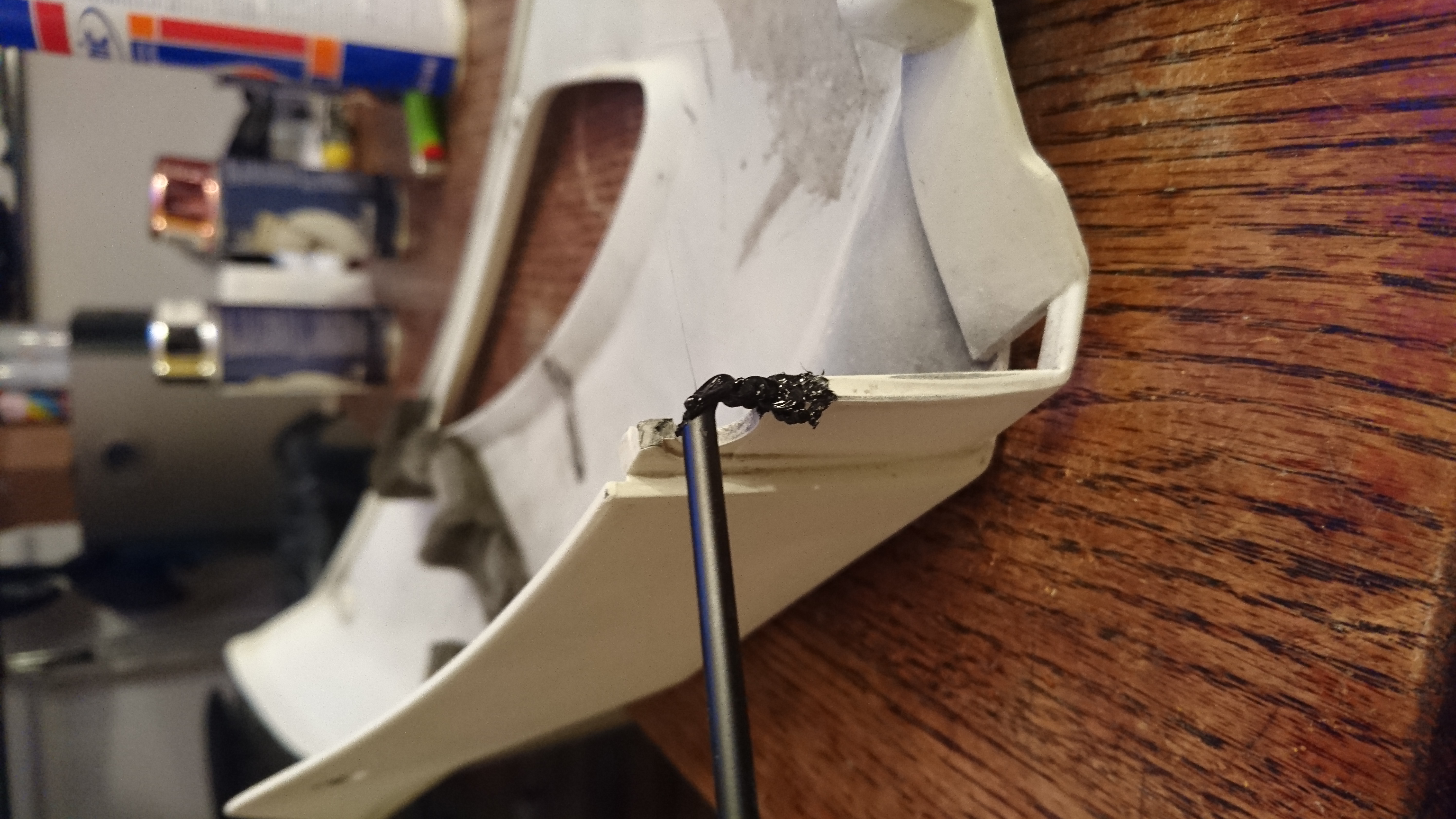
Start by making a string in the direction you intend to build the plastic.
Starting to build up ABS
Continue injecting material, adding a good 2mm in thickness all around it. This will insure that the core of your new part becomes solid and that the piece is not full of tiny holes and gaps once filed down.
It’s important to inject a lot of material and avoid gaps with air.
Keep re-melting the plastic and insert more plastic to make sure it’s solid.
Redrilled and filed into shape.
After filing the piece down you might see small gaps. There is no harm in reheating and add more material if you see gaps.
A couple of coats of primer later
Only thing missing now is a few layers of paint and clearcoat and it will be as strong as new.
As i promised a lot of the future posts will be about hacking toys.
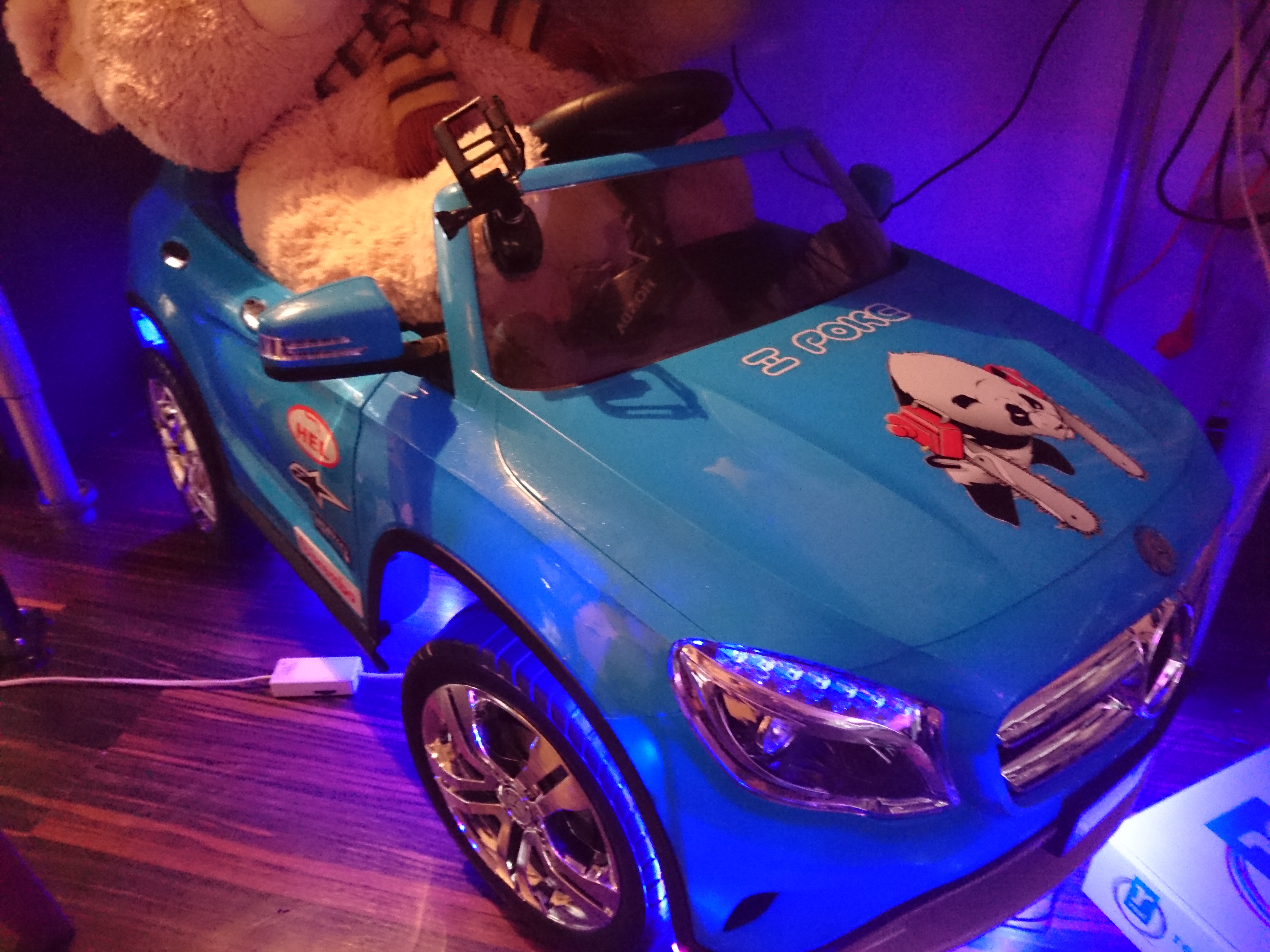
In November i bought this Mercedes GLA Class Ride-on kids car for my 1 year old son, a car he loves so much but i have a feeling he will never love less as this build progresses.
Its about 120 cm long, 60 cm wide, 50 cm high and weighs in at around 25 kilos.
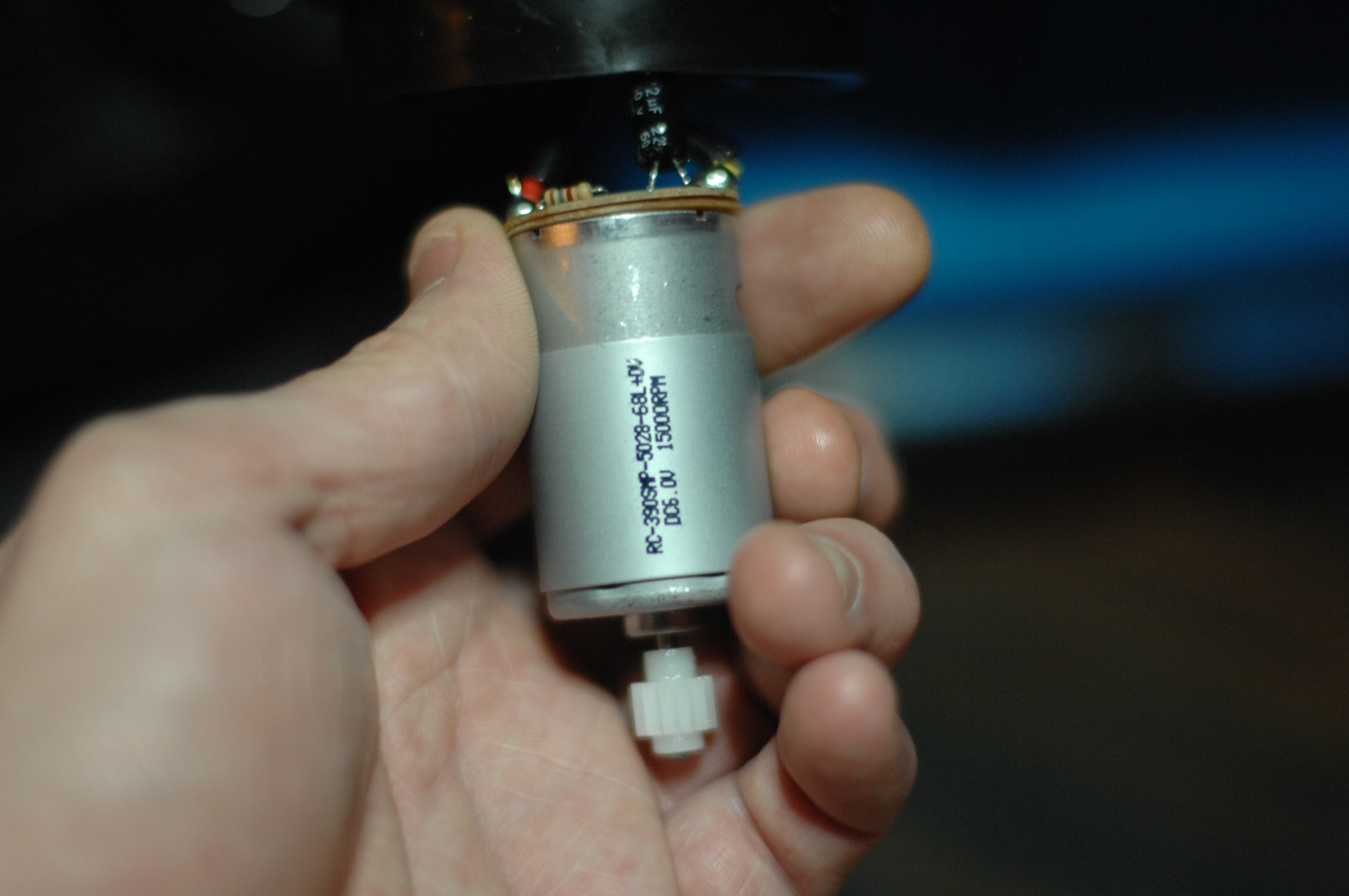
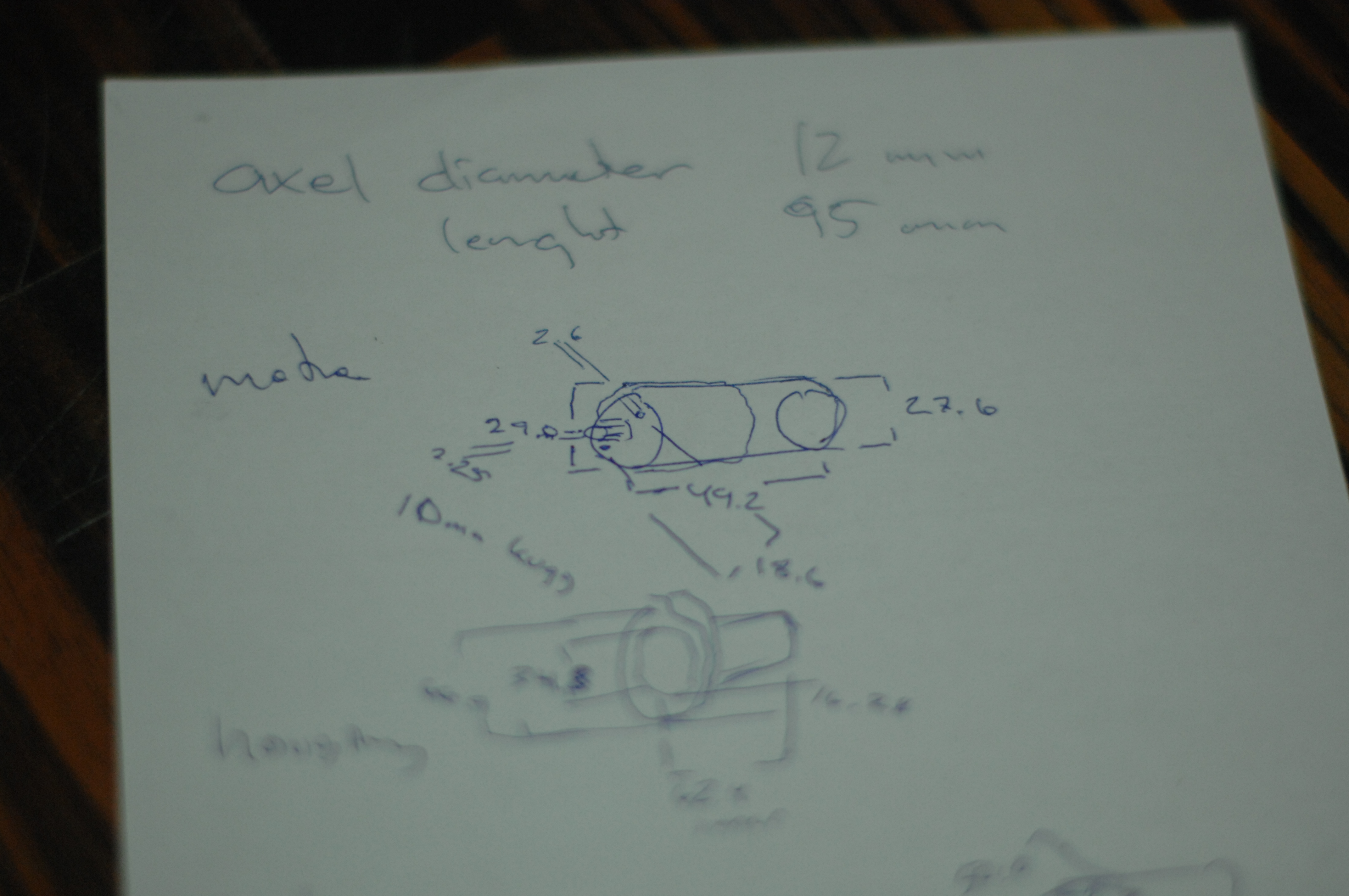
It costed about 250 euros and can be driven from the car or controlled by remote. The car has 3 emulated gears, each allowing the motors to higher rpm’s the higher the gear. I say motors, because this model have 2 separate 6 v engines (of type 380/390) which are serial-connected to the 12 volt relay in the receiver. The top speed is 5 km/h. The engines the car came with:
RC-390SMP-5028-68L DC6.V 15000RPM
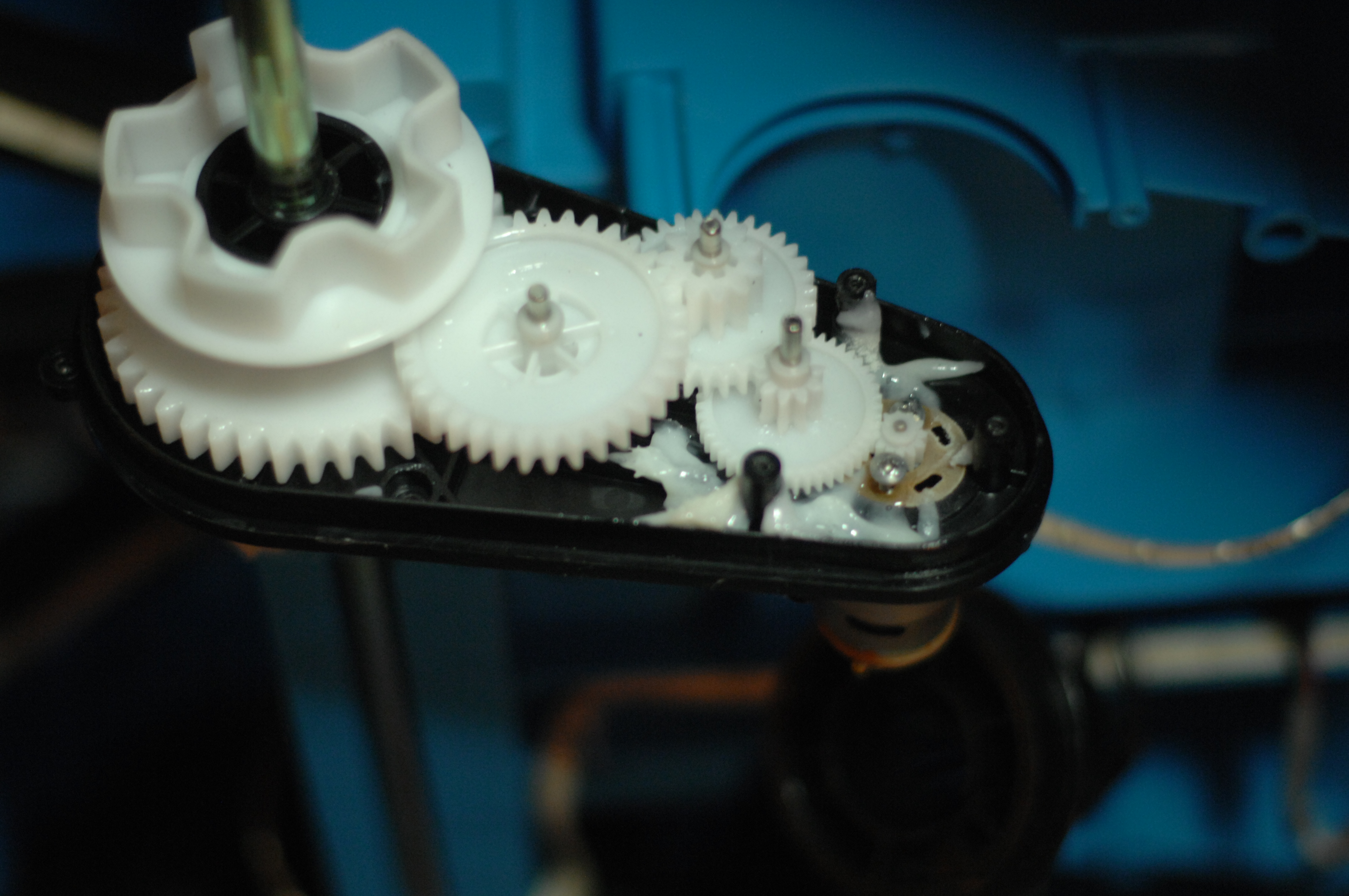
Gearboxes use all-plastic cogs, which is all good in it’s original state, but this might have to change to support what i want to do:
Knowing nothing about the motors (initially that was) i took some measurements and started to google:
The controller is kind of a all-or-nothing switches, which makes you zig-zag to the left and the right to keep a straight line while driving it using RC along narrow curbs. They added a acceleration lag in the power-on to soften the jerkiness a bit, but unfortunately they didn’t not managed to do the same when dropping the gas, so stopping is pretty abrupt.
Additionally it has a 6 songs “stereo” , with a 3.5 mm stereo-plug. The songs are well composed mixture between kids music and electronic dance but 6 songs gets boring fast so this is on the change list. When pushing the start-button you hear a roar of the motor, and pushing the horn makes a “mepp-mepp-mep-mep” tone.
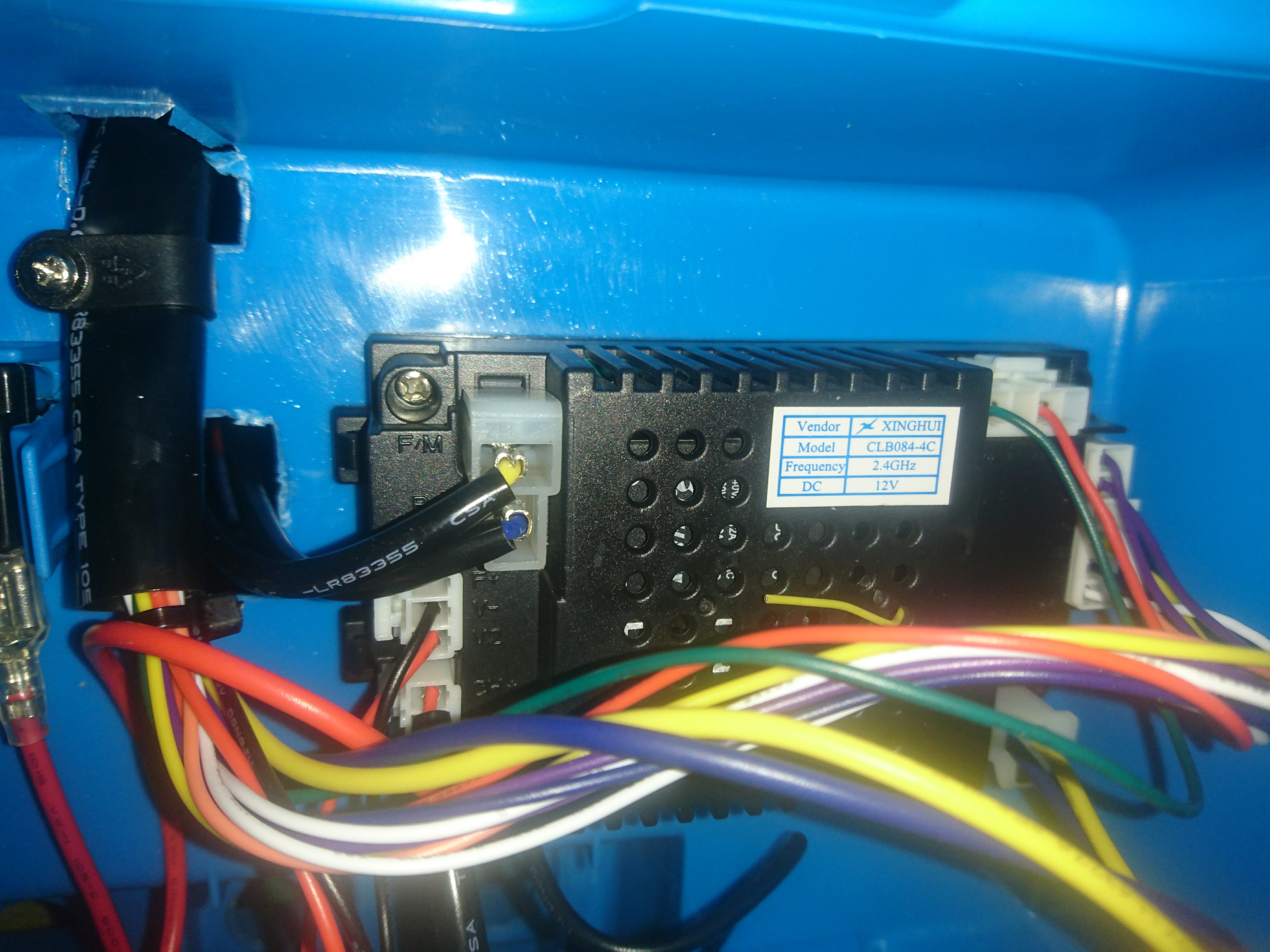
Xinghui CLB084-4c 2.4 ghz receiver, charger, motor controllers and stereo.
The receiver can be found on Aliexpress, but a pdf with all pinouts have turned out to be harder to get my hands on. That sucks, as I see pins that are unused meaning it might have more features I don’t know yet. Will reverse engineer it later. All in all it’s a funny toy for it’s price but a lot of improvements can be done.
So what am i planning to do with it?
Well, i have a lot ideas but some cost a bit of money and some are hard to source parts for and some will simply be unsafe.
It should be a little faster, with softer acceleration and braking.
Replace the radio-controller/receiver, with something a bit more professional, less jerky and with lots of spare channels to control all the electronics.
Proper rubber tires giving traction and look better. A few options out there, but I haven’t found exactly what I want.
A proper stereo with some umpff!
Individual brake disks on the front wheels to be able to do burnouts.
Melody horn.
Proper seat-belt 3 or 4 point, new seat even?
Let’s get started.
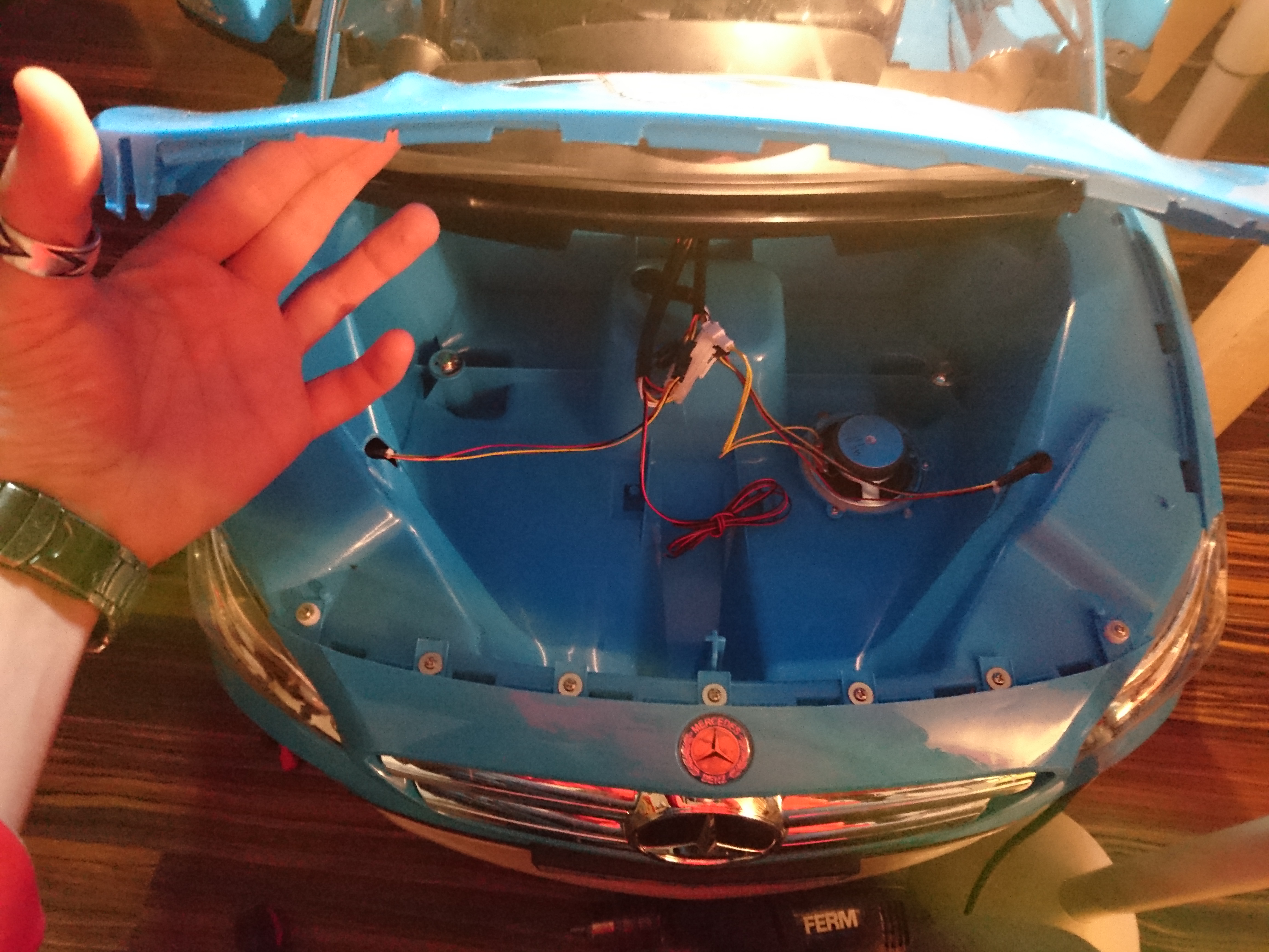
The first thing that struck me when i started screwing it apart was how much space there is left in it. The the hood is screwed down, but once unscrewed yet another gigantic rather empty space is reveled. Same goes for the trunk. Ohhh the potential :)
So where does one start?
Let’s go with the low-hanging fruit. Nothing says car-tuning like RGB LED-stips, and it’s something my son would notice directly so that’s what i went for. End result looks (and sounds) something like this (hosted video on youtube, as i slashdotted my hosting company yesterday thanks to HackerNews):
A second fast win would be stickering it with some AlpineStars, Brembo, Hel performance and GoPro stickers. I had a left-over “i poke bear”-sticker from the pimping of my zx636 ninja, so that went on the hood too.
Speaking of the hood, i mentioned i opened it up however seeing the hood open made me think it should not be screwed down ever again. I made 2 temporary hinges with a glue-gun and two screws, and cut off the majority of all the flanks that held the hood into place making the area easily accessible for future upgrades.
The open hood reveals a lot of free space and a mono speaker.
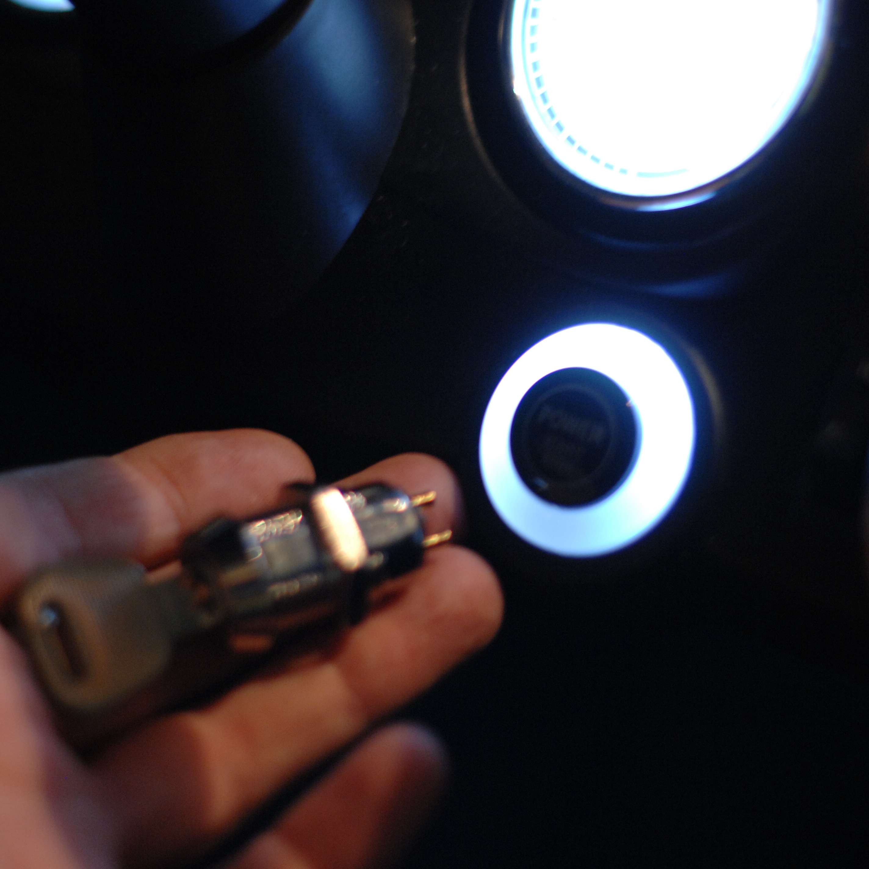
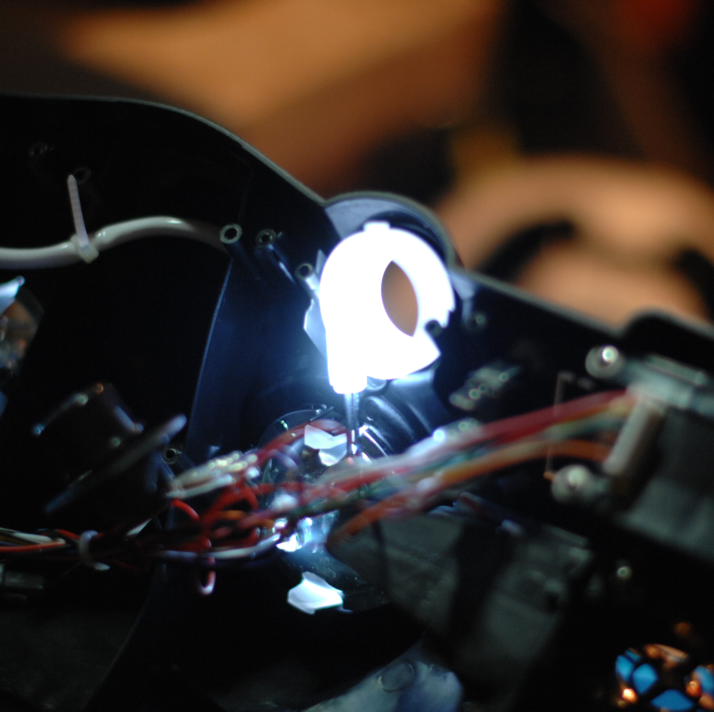
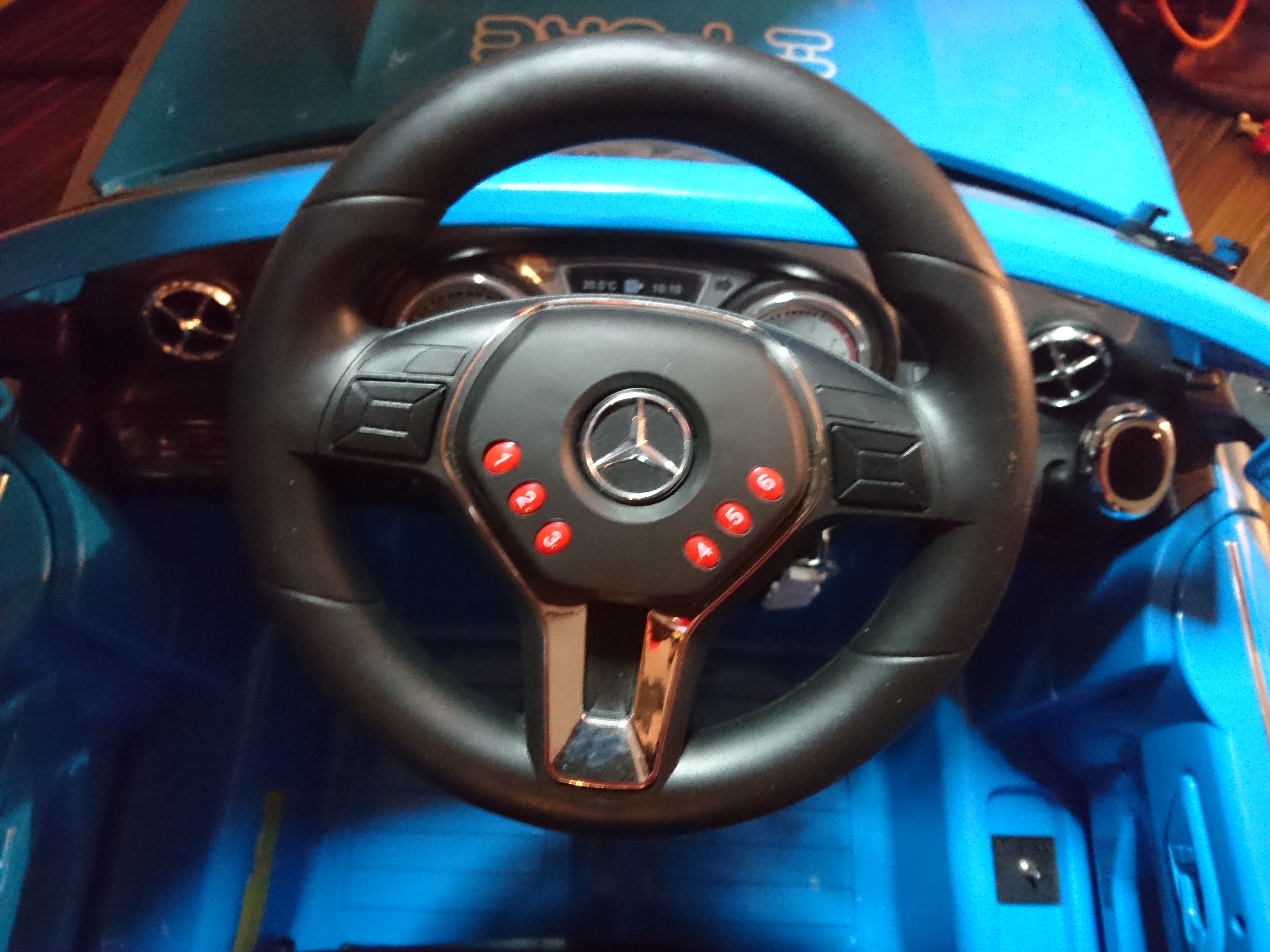
Ignition-switch:
My little guy is totally fascinated by keys, so needless to say he needs an ignition-key. I found this little switch in one of my favorite stores around the corner, Rotor-radio Amsterdam.
To get it into the car, i had to unscrew large parts of the car.
Then solder it into the harness where the old switch was connected.
Tada!
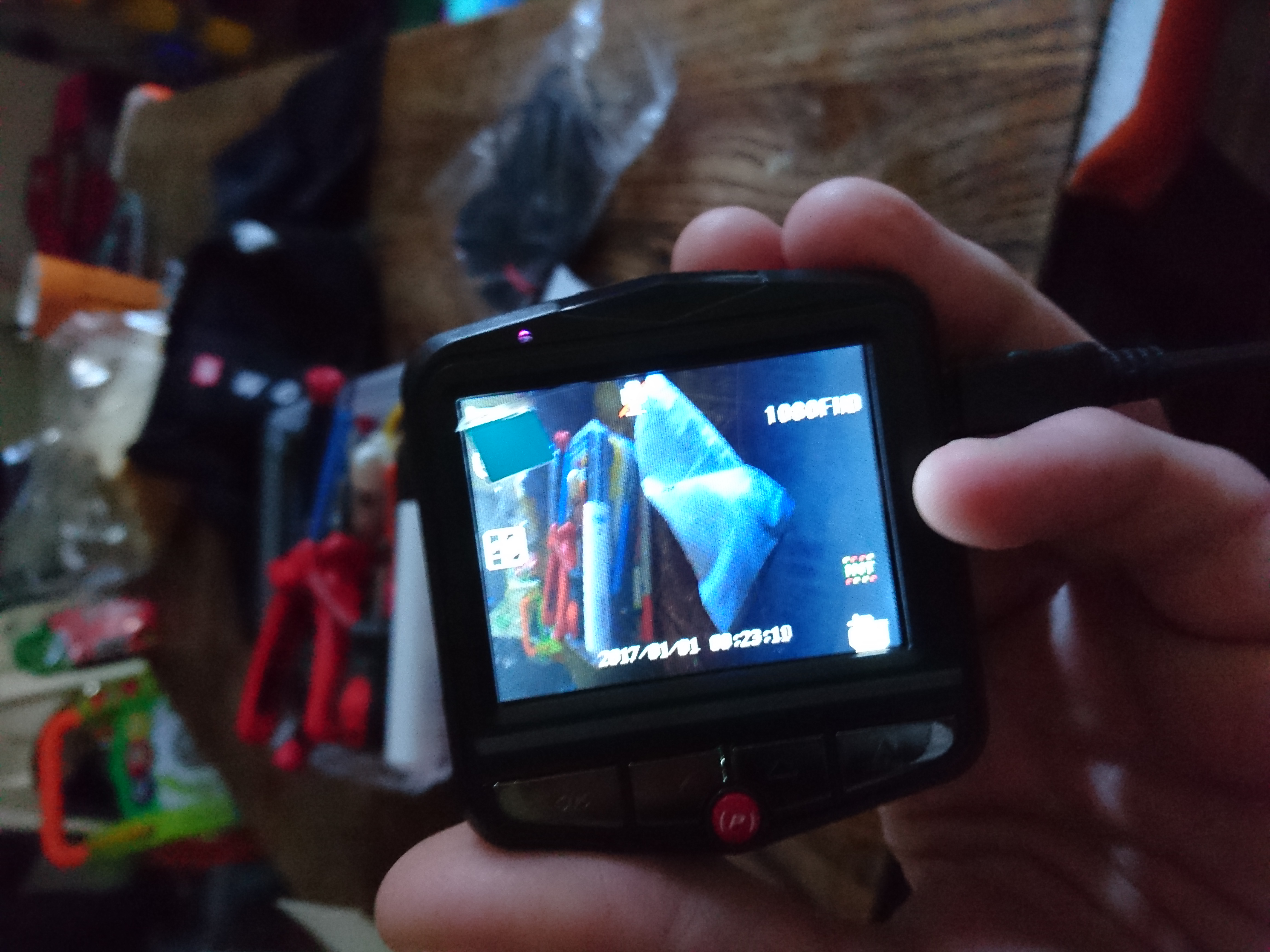
Reversing camera.
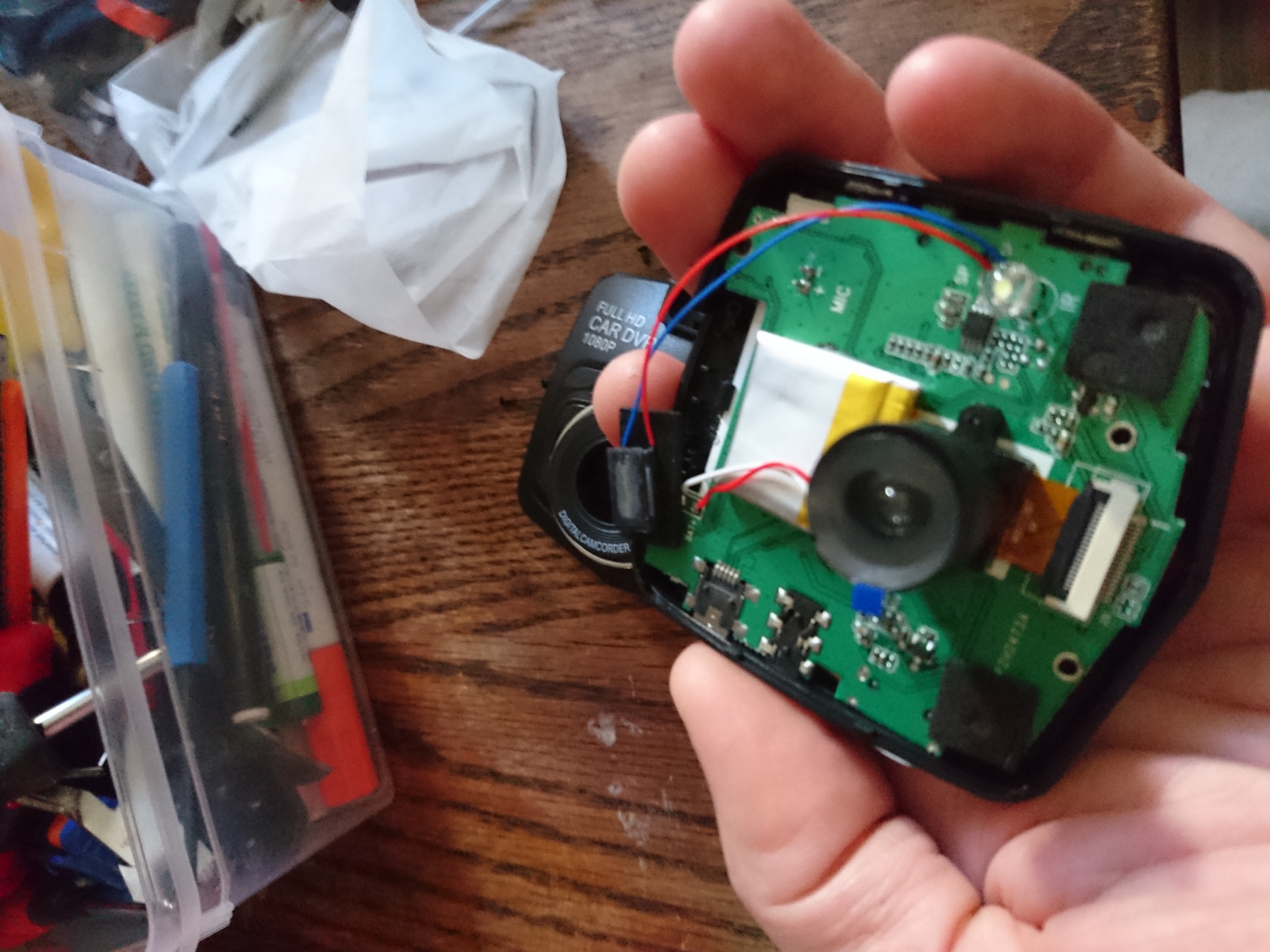
I found this super-cheap dashcam, and decided it would make a great rear reverse camera:
Quality of the picture is great and it also has night-vision :)
Opening it up, shows i will have to solder 17 wires to separate the camera from the circuit-board:
Not impossible but since i intend to install a proper stereo in the dash too, it makes sense putting this on ice until that is done and I know how much space is left.
I got the power!
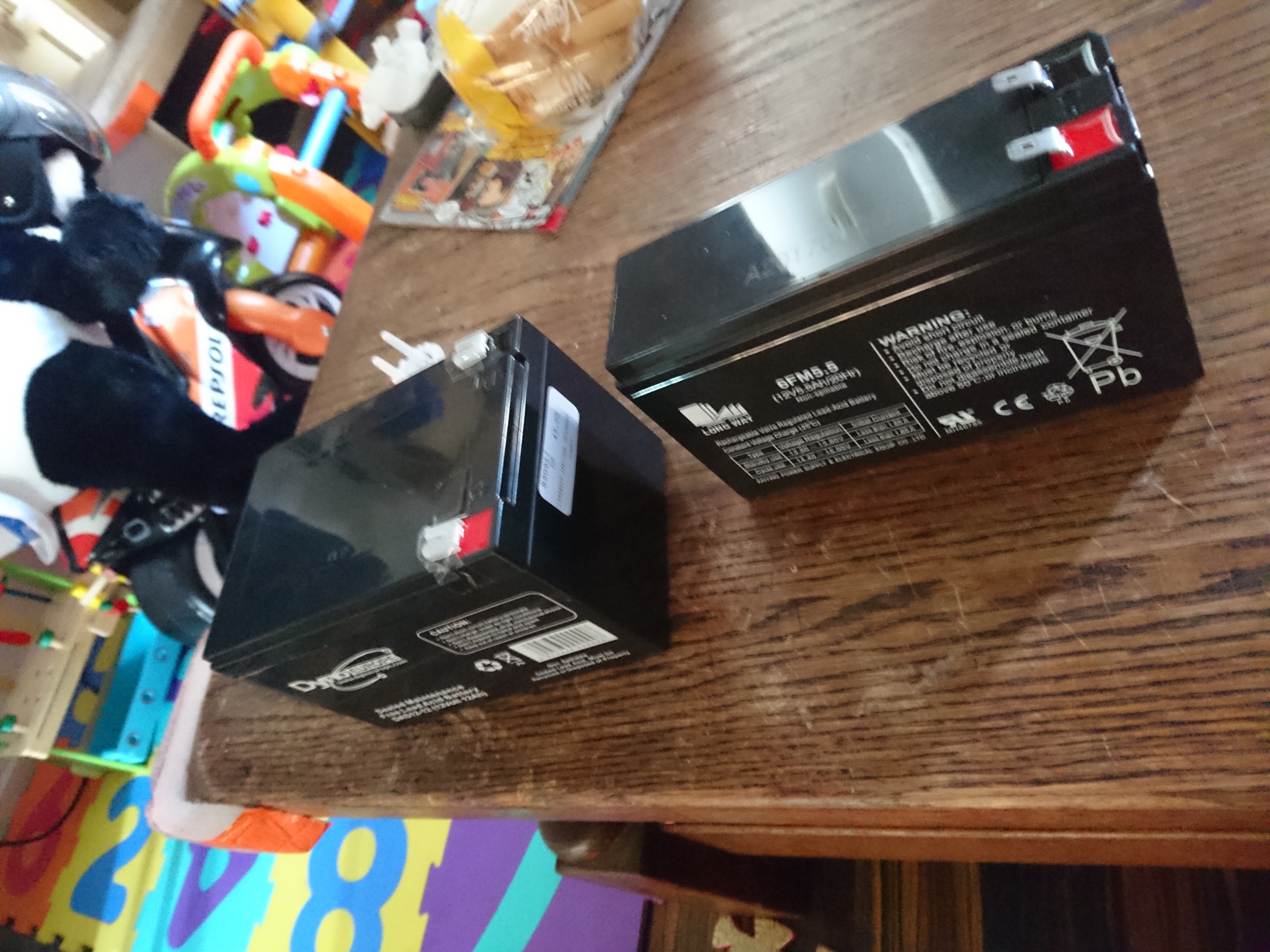
So far i have not run into the limitations of the battery, but my son is quite young and we only do small rounds with it. However i plan to stick a lot of electronics in this beast so a larger battery makes sense. The car actually had room for the larger battery where the old one was mounted
I replaced the 5.5Ah 12 volt lead-acid with it’s 12 Ah big brother.
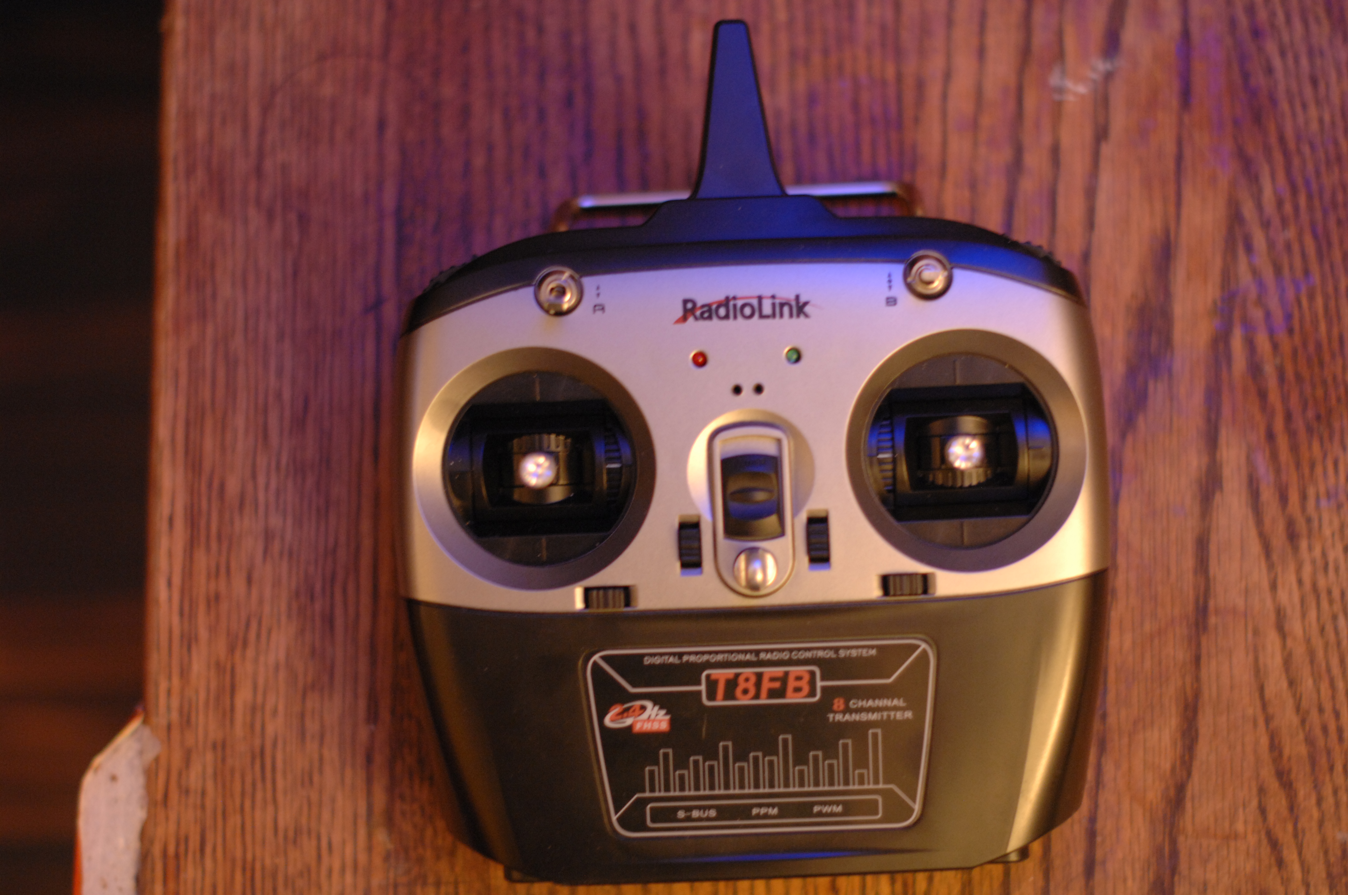
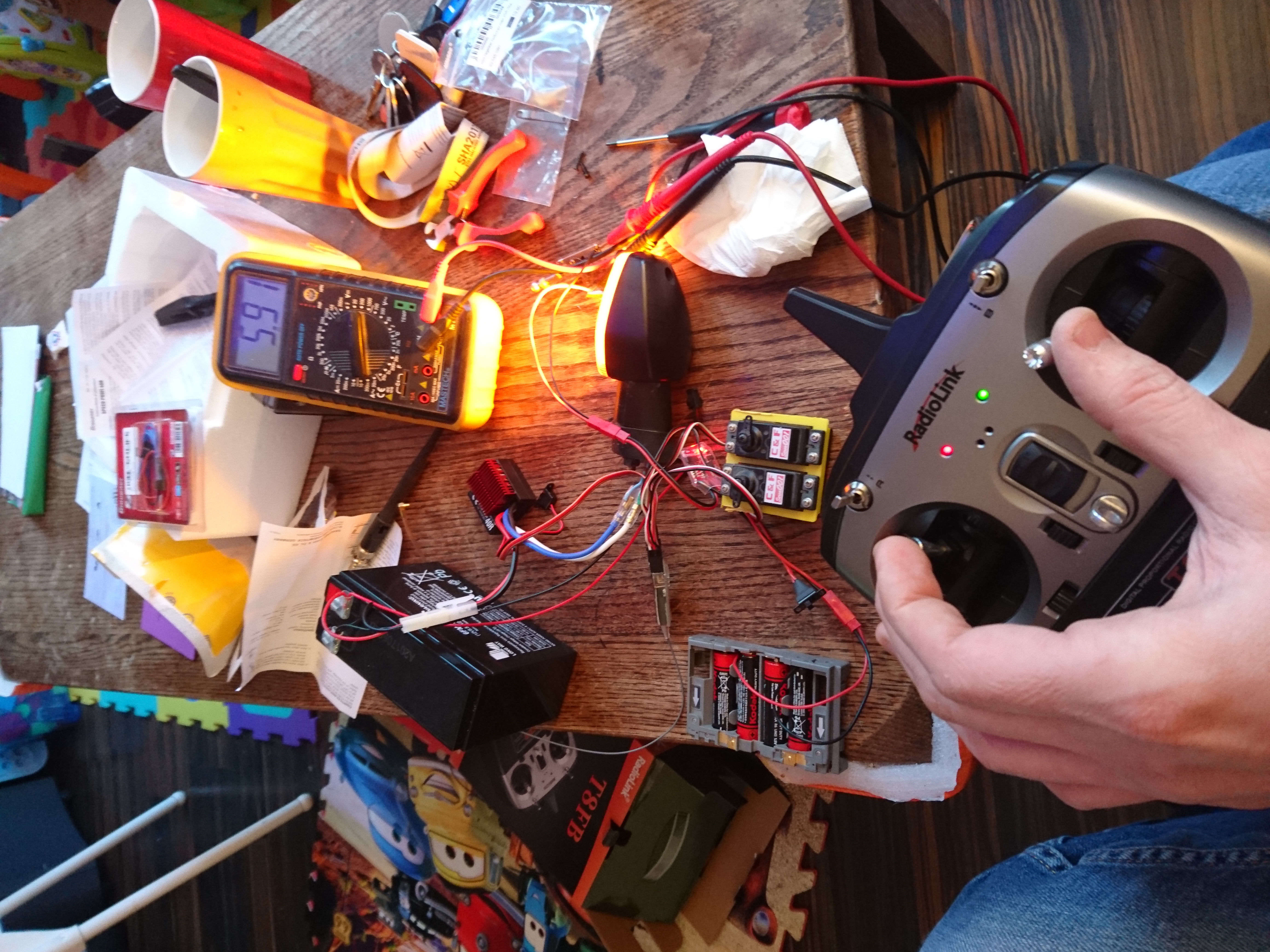
With brakes, LEDS and what-not, i decided to buy a 8-channel radio. I can only hope this scales to the ideas i have but we will see:
RadioLink T8FB
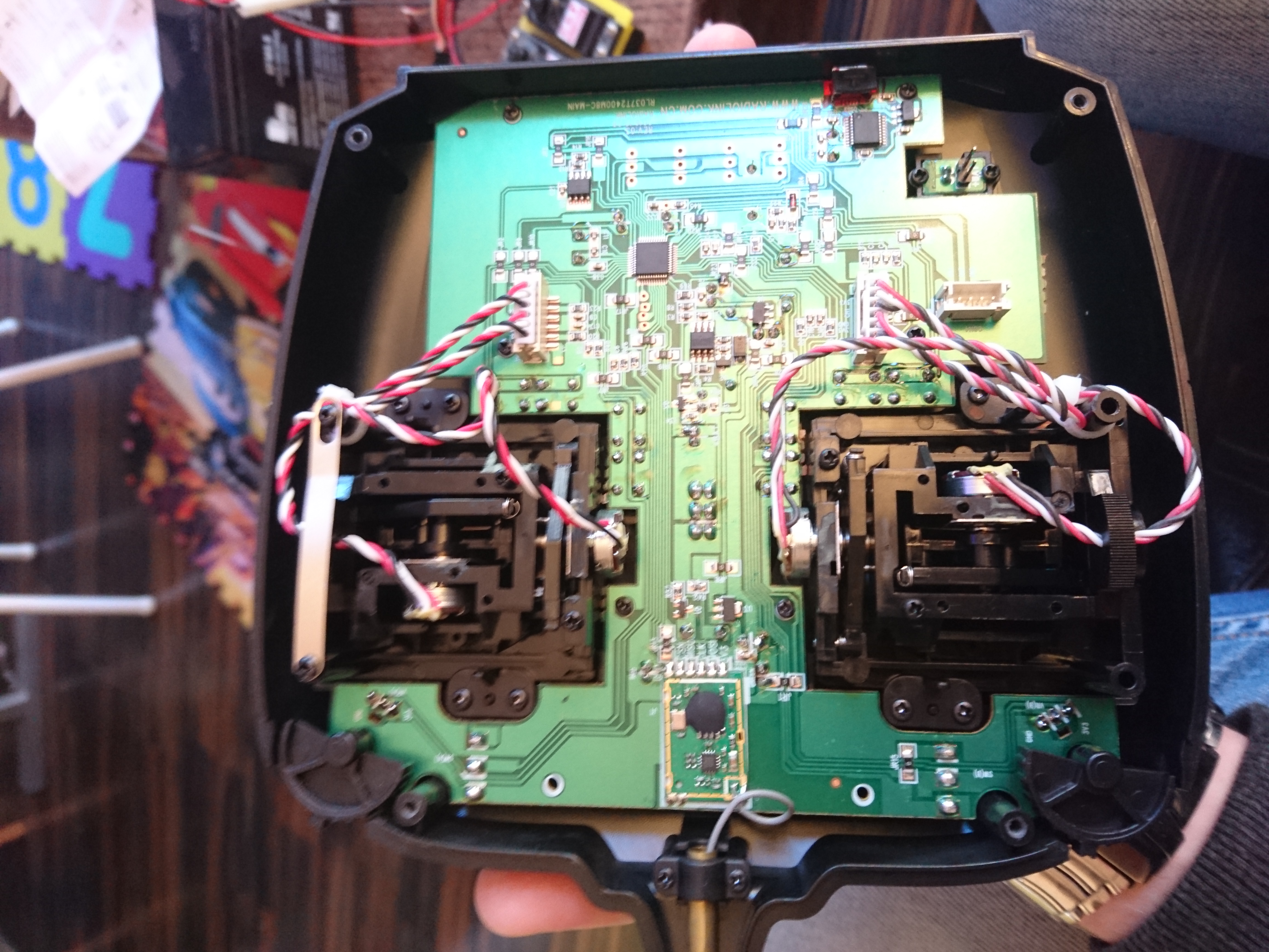
Getting the radio ready!
I have never built a radio-controlled car from scratch so selecting ESC, servos, motors, batteries was all done ad-hoc, while googling around. This radio is intended for plane/helicopters, so i started by reconfigured the control to spring back the left hand stick when released:
RadioLink T8FB opened up.
For the drive-line i choose a 40Amp 12 volt ESC from Graphner. Two old servos from a small electric plane simulated the servos for the brake-disks and a smaller ESC to control steering.
The old fireblade blinker is connected to the 40Amp ESC to verify that all works. Having it all on the table like this allowed me to calibrate servo’s and ESC’s in a simple way.
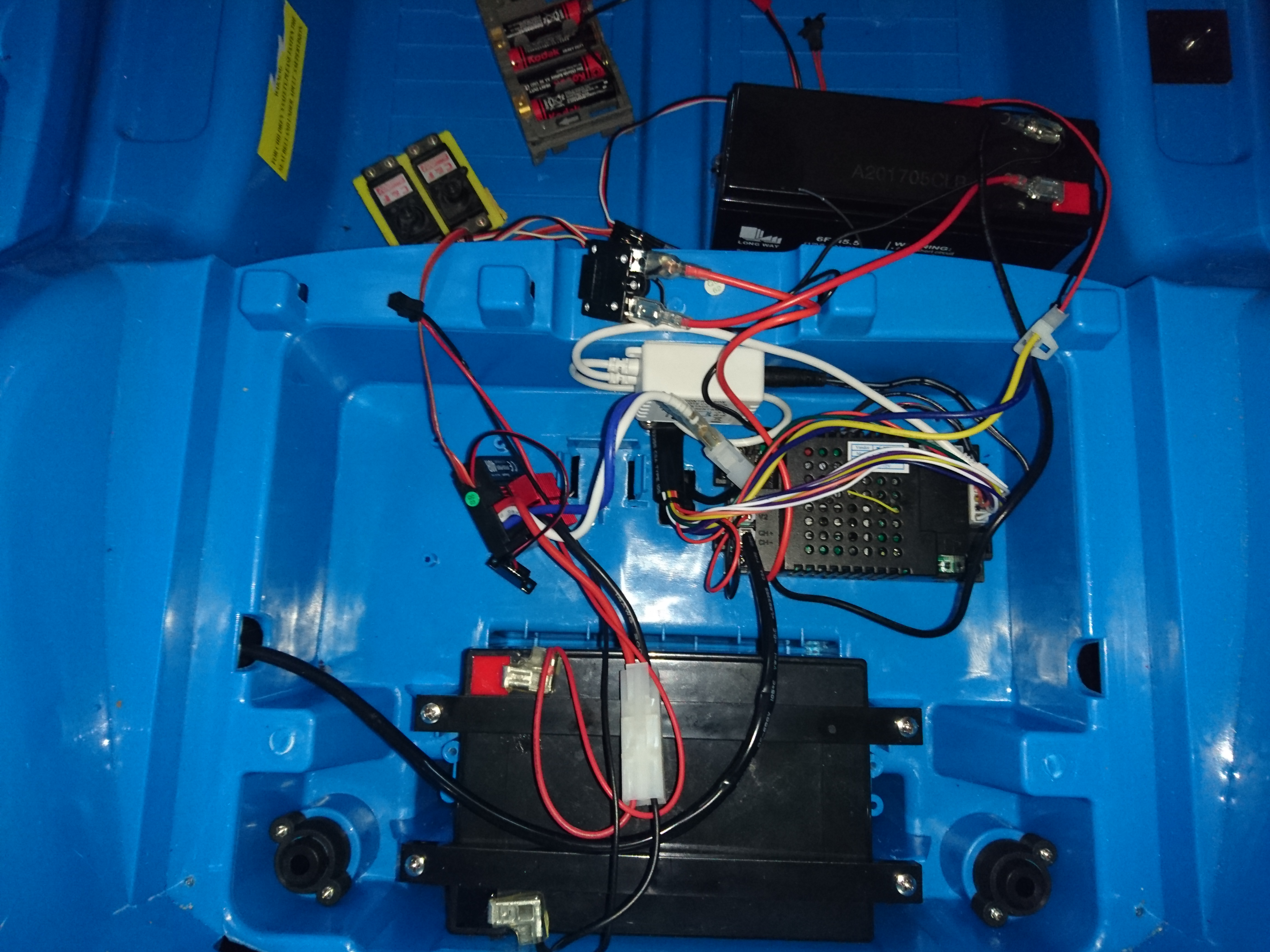
Once that seemed to be working i hooked it up to the car. As my son would be very sad if his stereo did not work, i left as much of the old electronics hooked up in the birdsnest you can see below:
Nested the new rc-parts into the original wiring, and it works.
This means that i now can control the car over the 8 channel radio, while still providing power to the old electronics that allow the fake engine sounds and “stereo” to work.
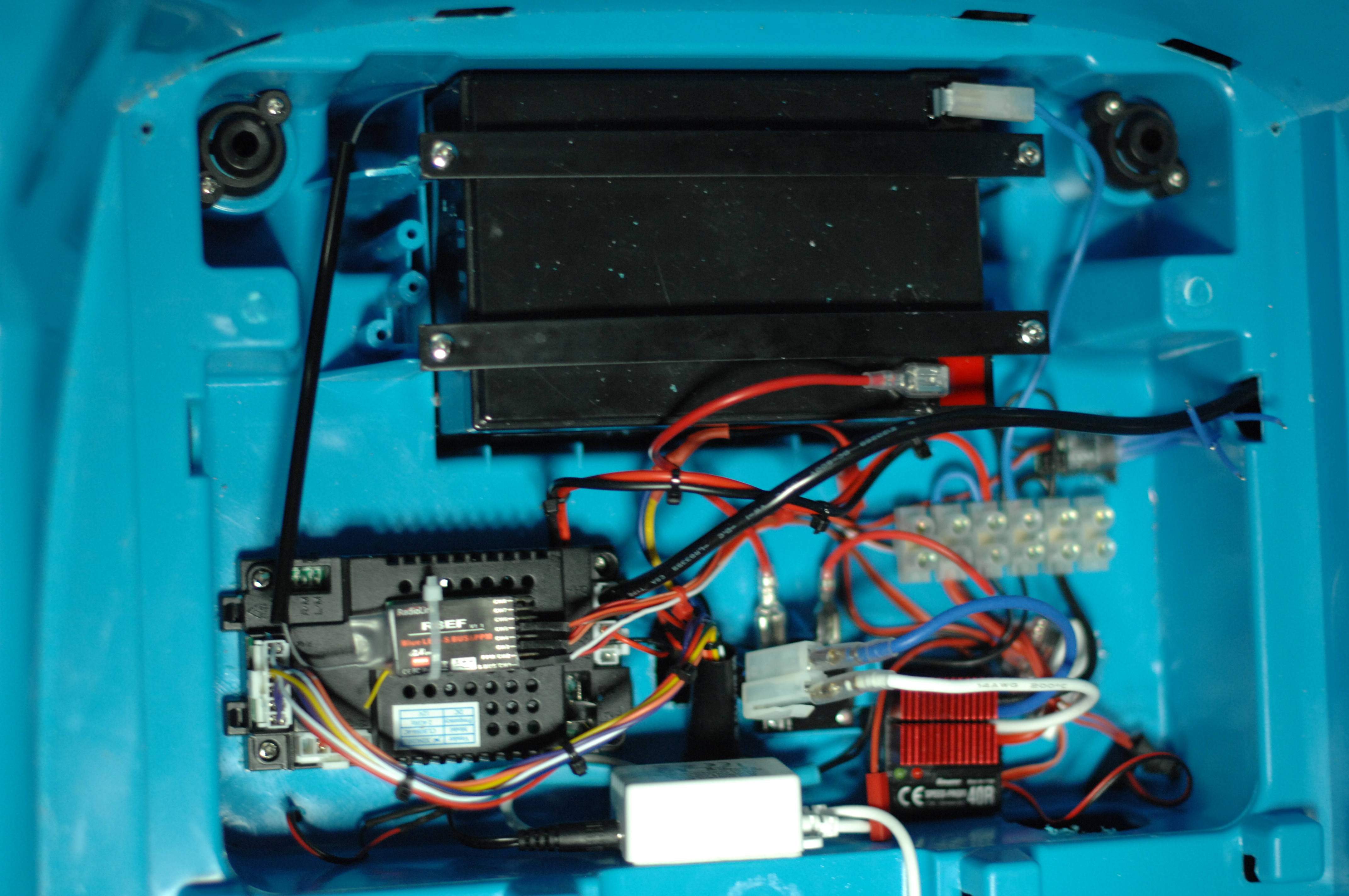
After a bit of tidying up, it is starting to take shape. Doubt it will look like this when i am done, but lets see.
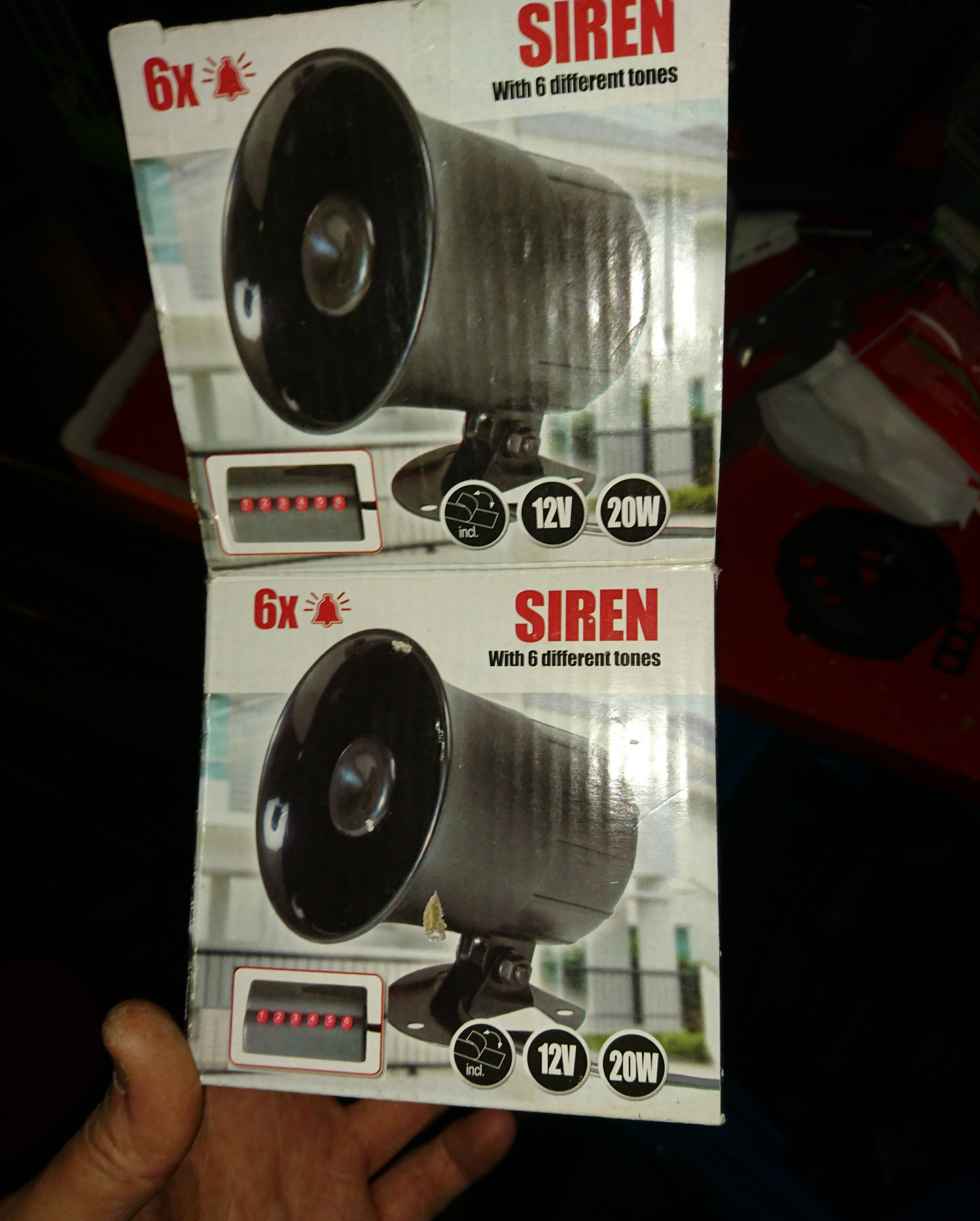
Can you hear me?
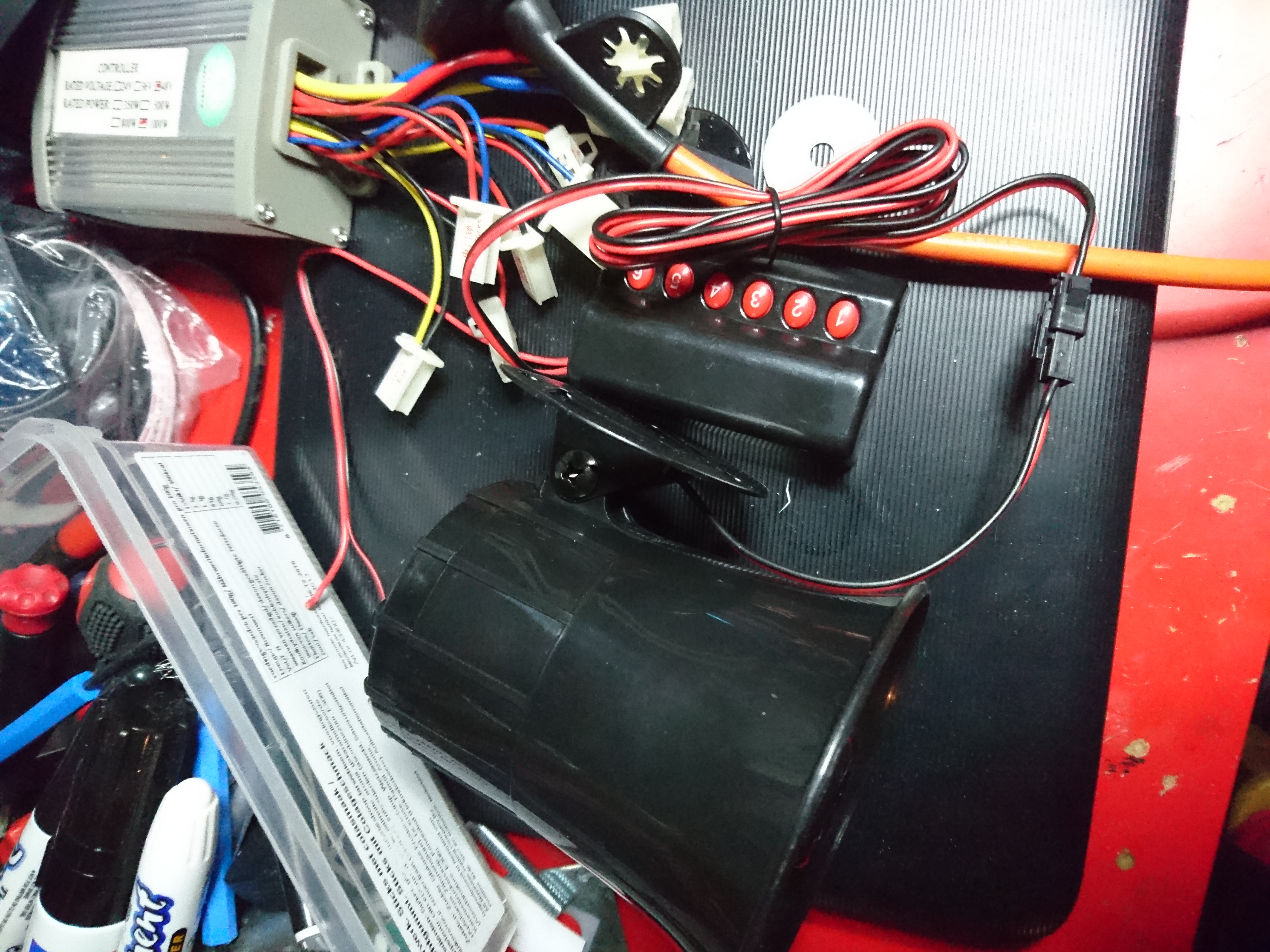
Speaking of sounds needless to say he needs a proper horn. I found this 20 watt siren with 6 tones for less than 10 euros, so that’s going in.
I don’t know how loud it is, but it’s f***ing loud.
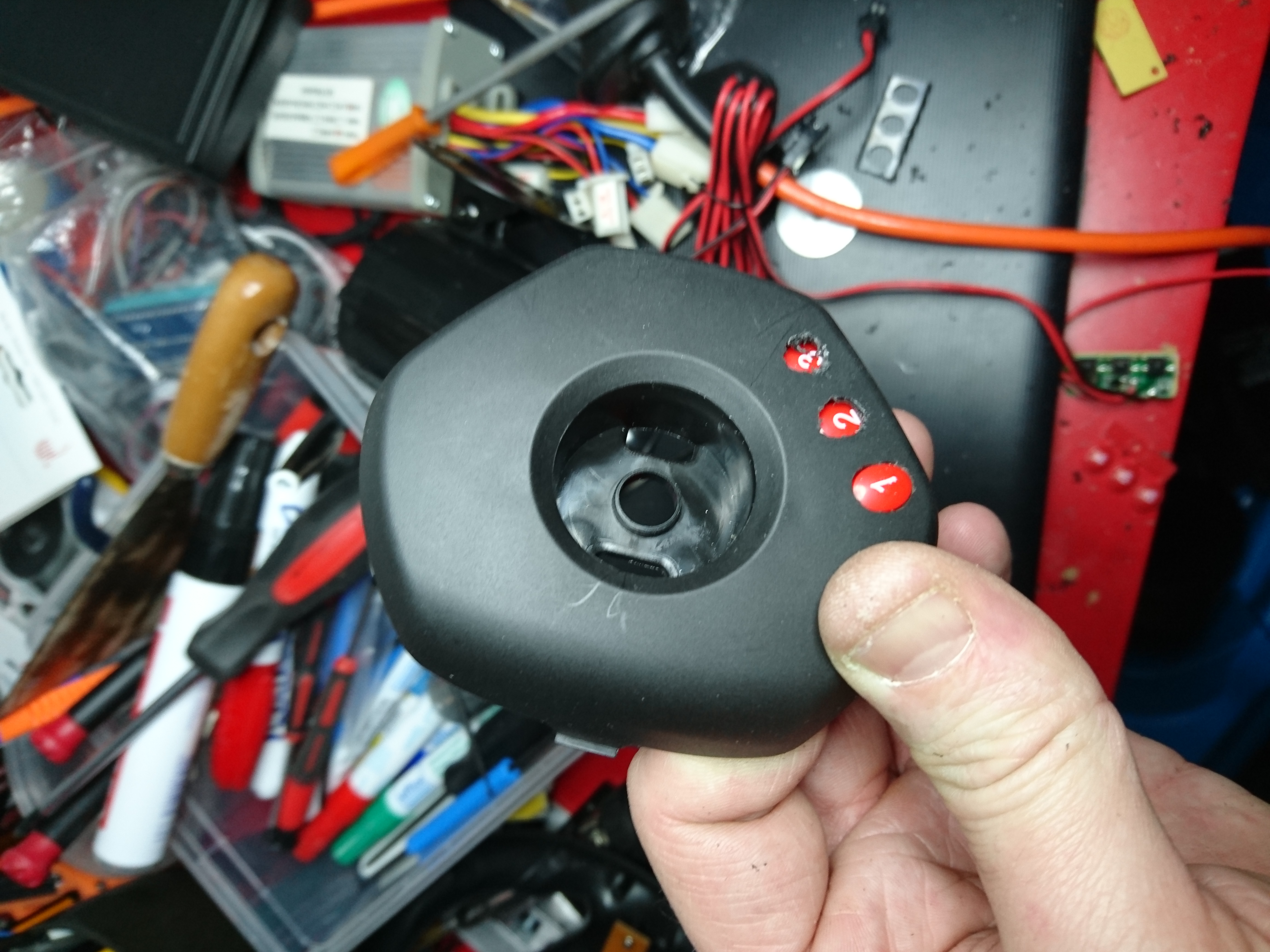
Adding the ugly keypad on the dash would have been a five minute job, but as i mentioned i want a stereo in it at some point and space is of the essence.
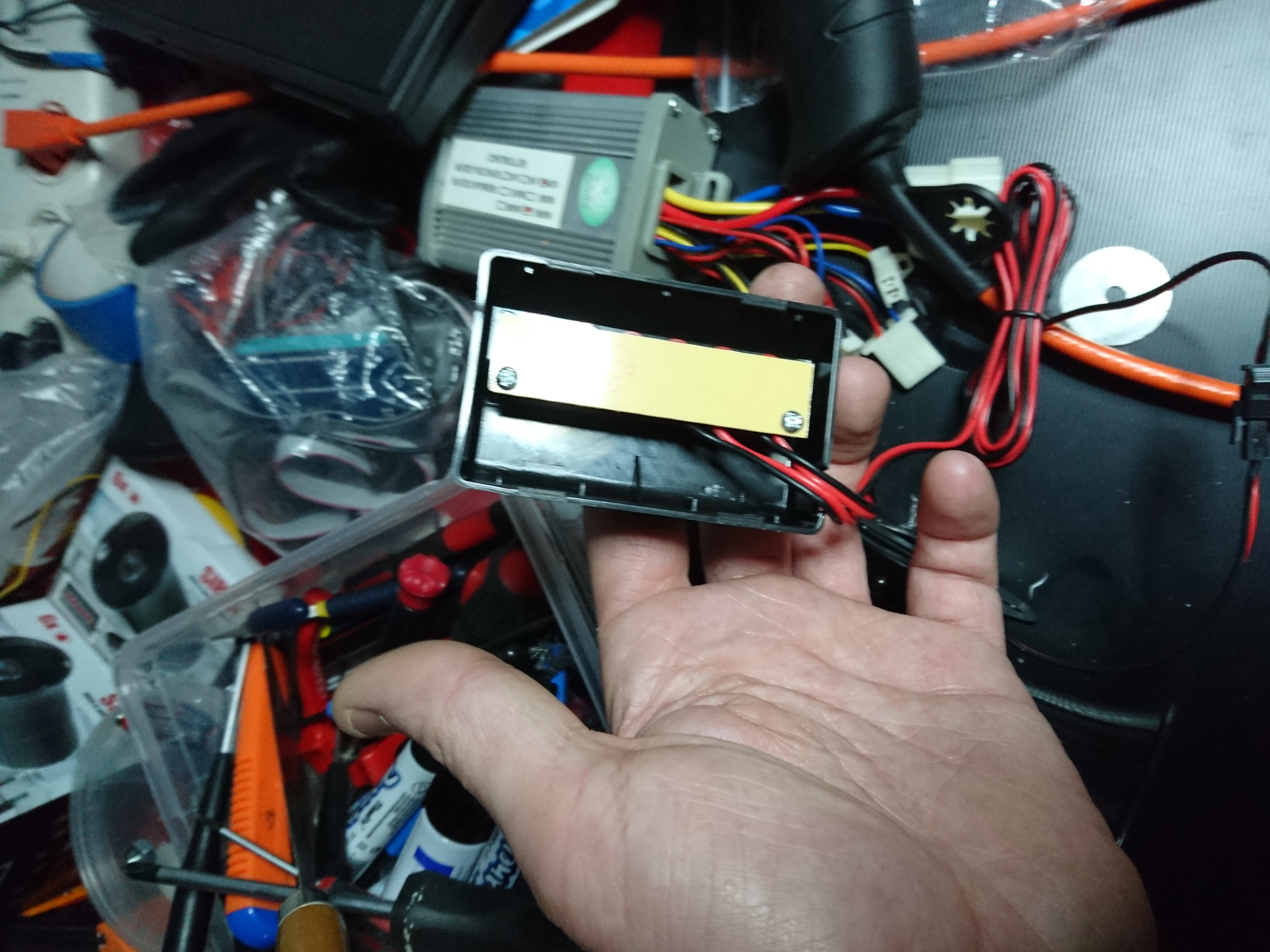
Inside the keypad is a tiny circuit-board that i could make fit inside the steering-wheel, but to fit the center the steering-wheel, it will need to be chopped up.
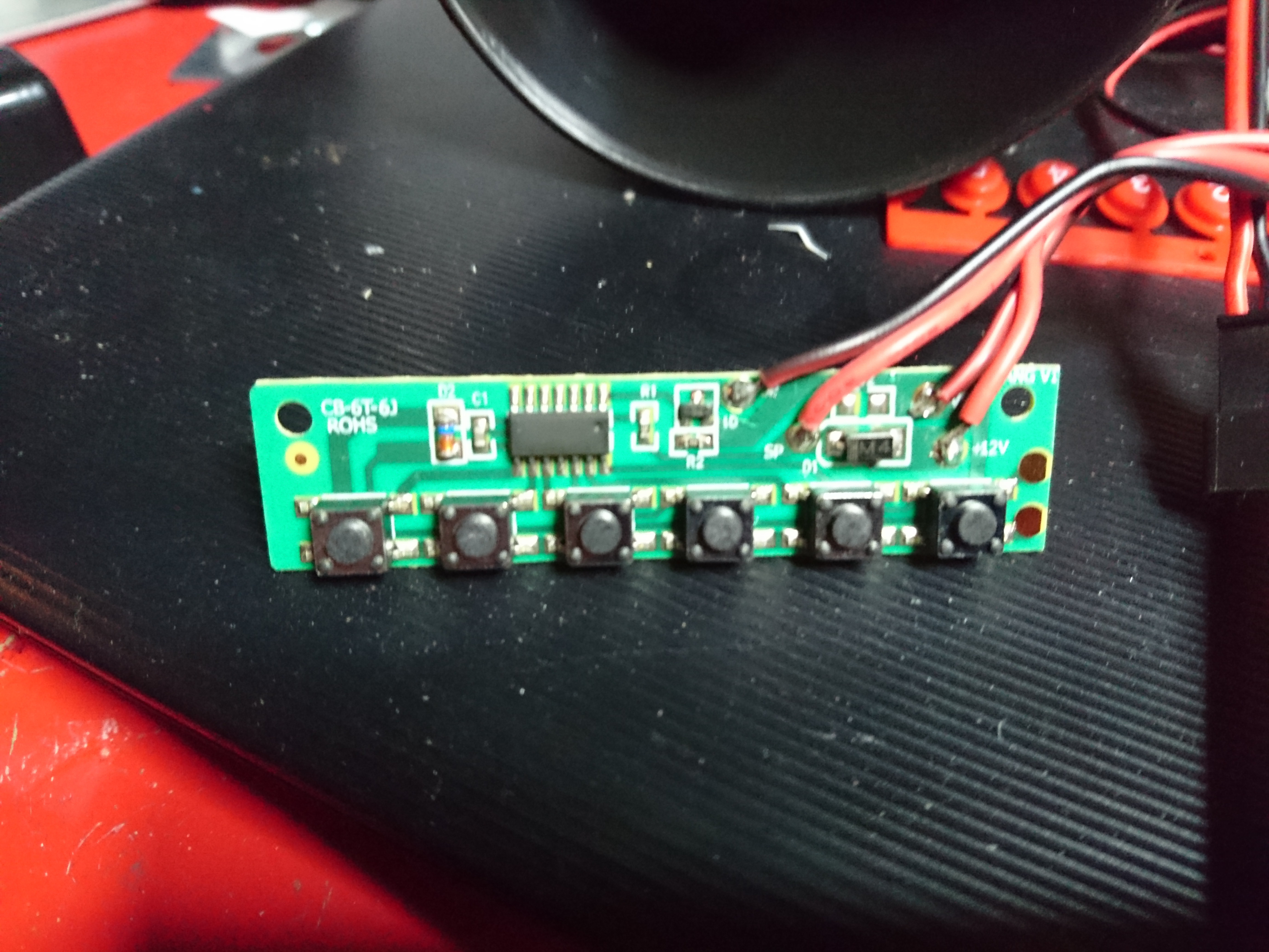
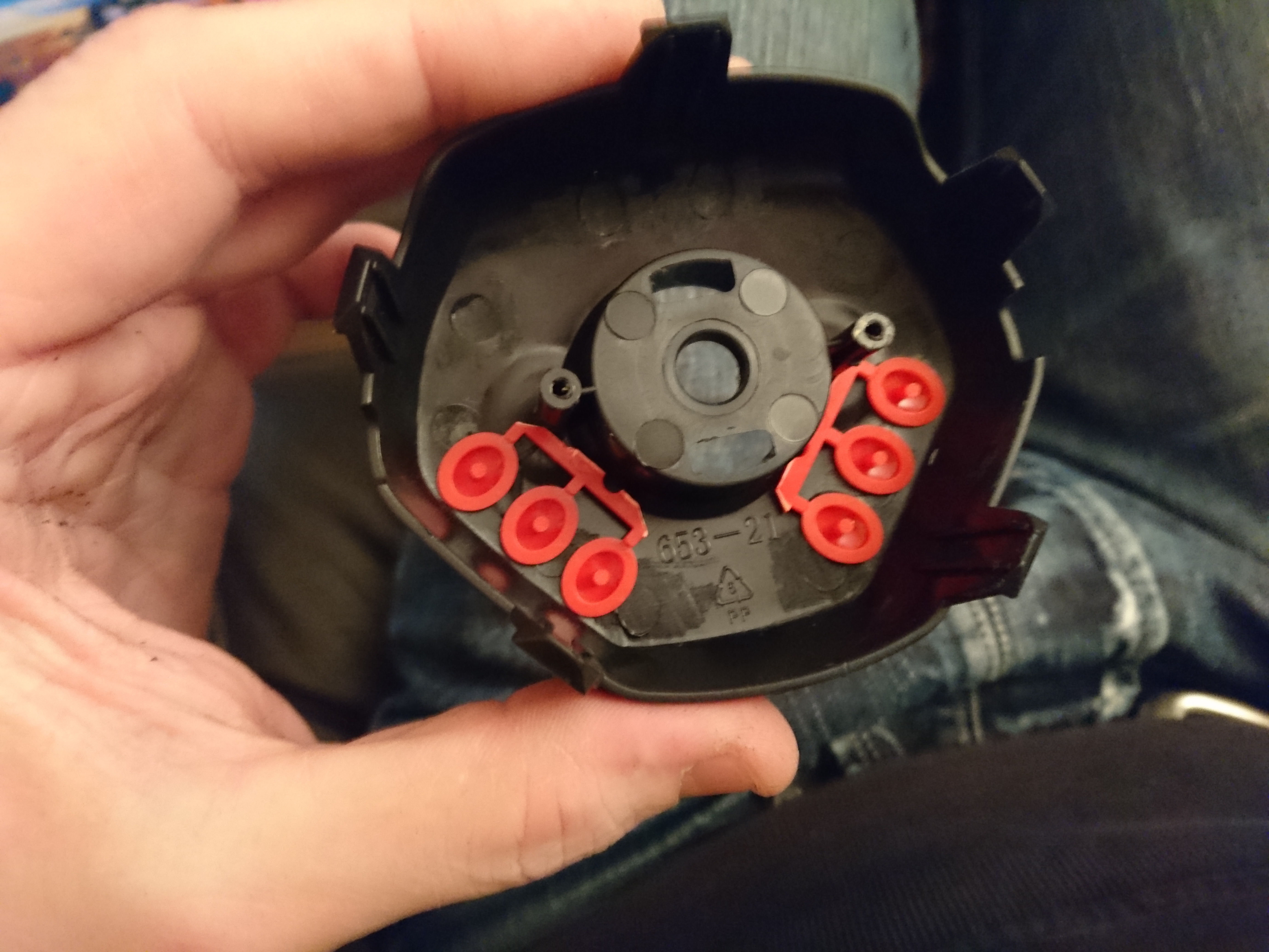
The best part about cheap electronic tends to be single sided circuit-boards which allow you to customize them very simply. I locate the place that has most free space around components.
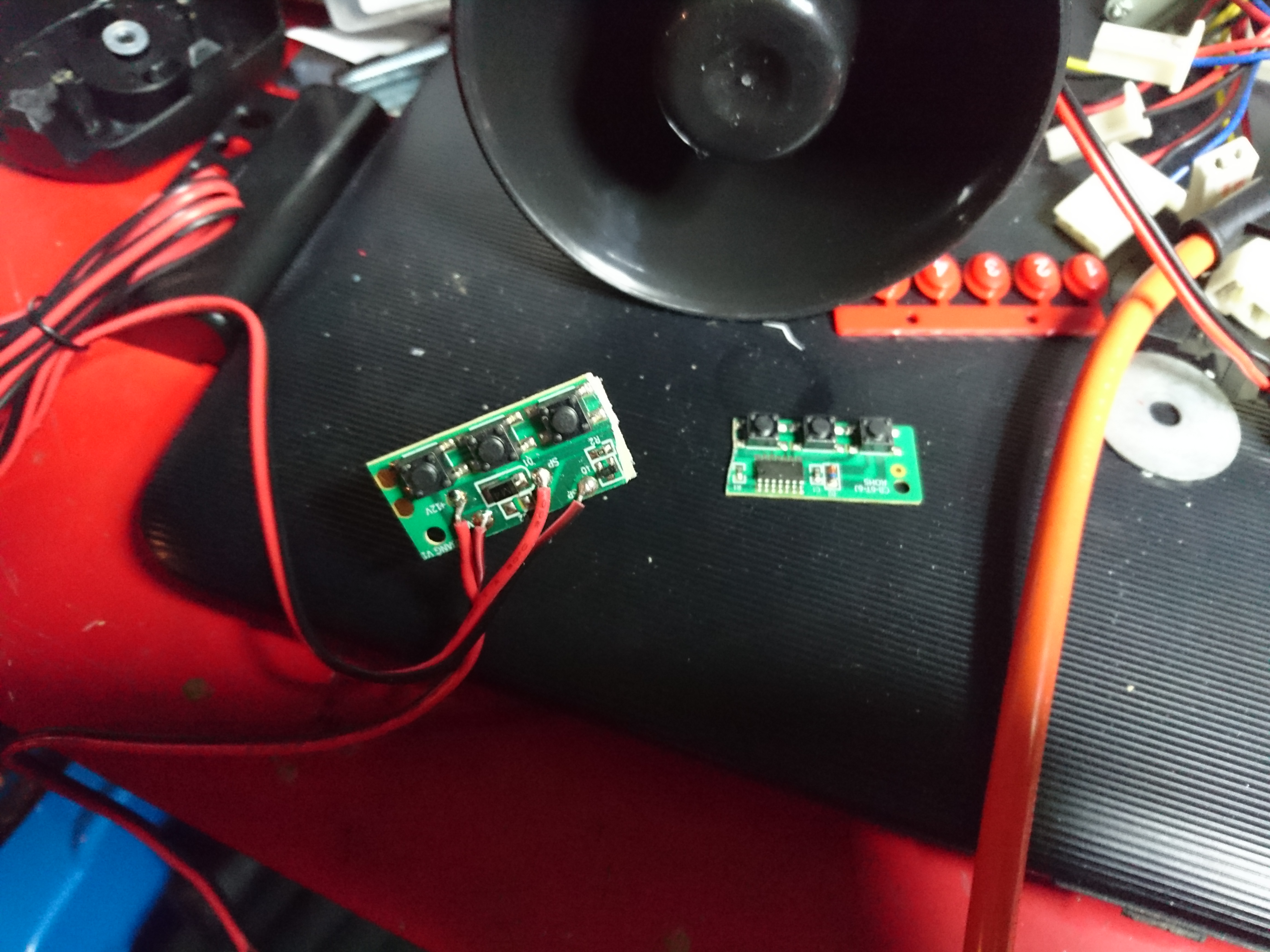
After doing some measurements and make sure it will work i use a hobby-knife to cut it in half, making sure i leave enough copper trace to solder cables on to reconnect the half’s.
Next i make a few pilot-holes and start the painstaking process of filing away on the plastic. Not scratching it in the process is an art i still don’t master.
The buttons needs to be trimmed down to fit the housing too. Two component glue fixes them in their position and make sure they spring back out again.
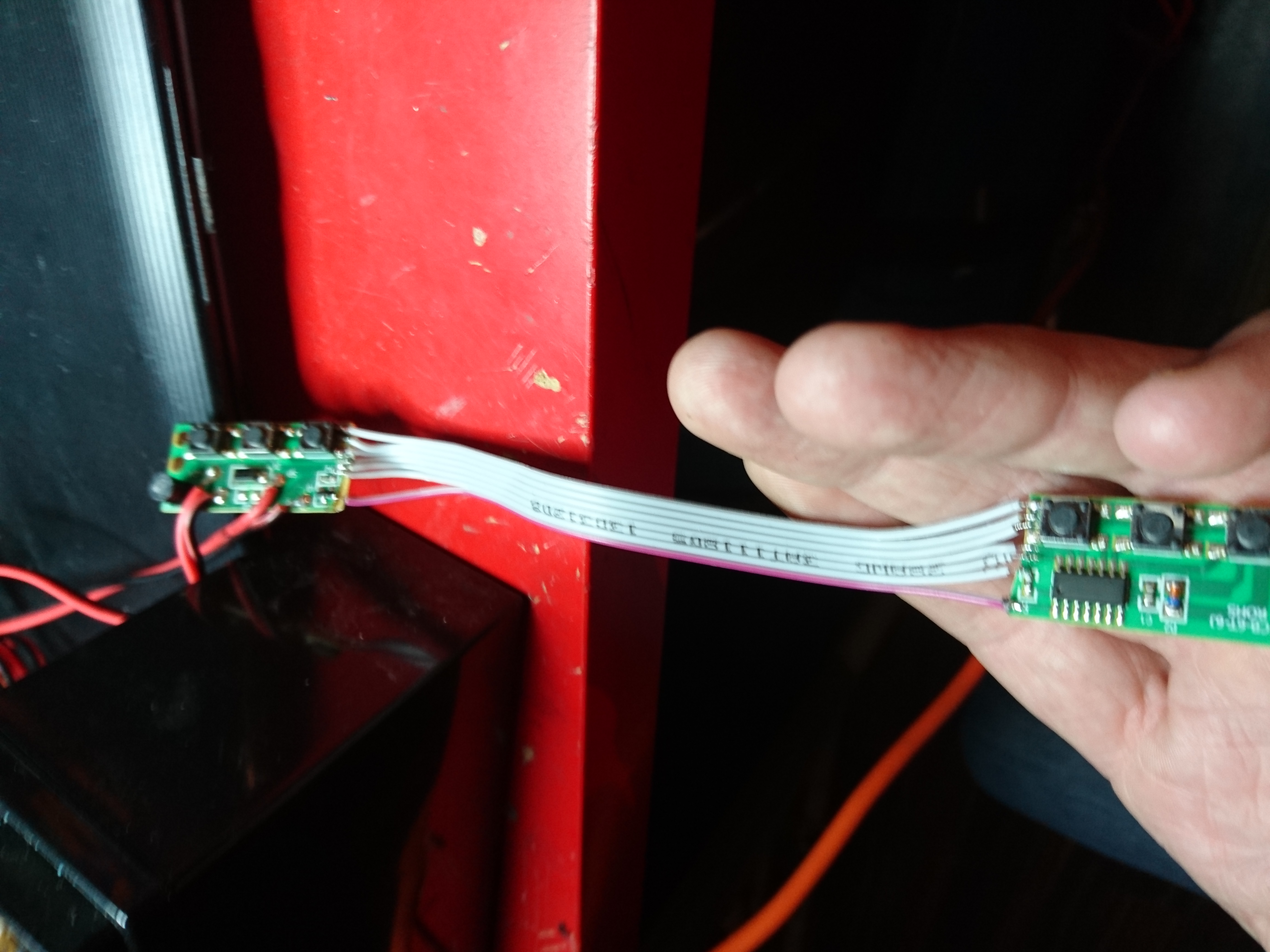
Once everything seems to fall in place i go ahead and solder it. Leaving this part for the end is critical as you are very likely to pull one of these tiny 14 solder-points and the copper it’s attached to if the cable snags later. I secure the ribbon cable with melt-glue to allow me to to be less careful when putting it all together again. The circuit board is screwed back in to new mount-points i took from the old casing, and the whole construction is secured in several layers of melt glue to make sure it can handle hard pushes without breaking of.
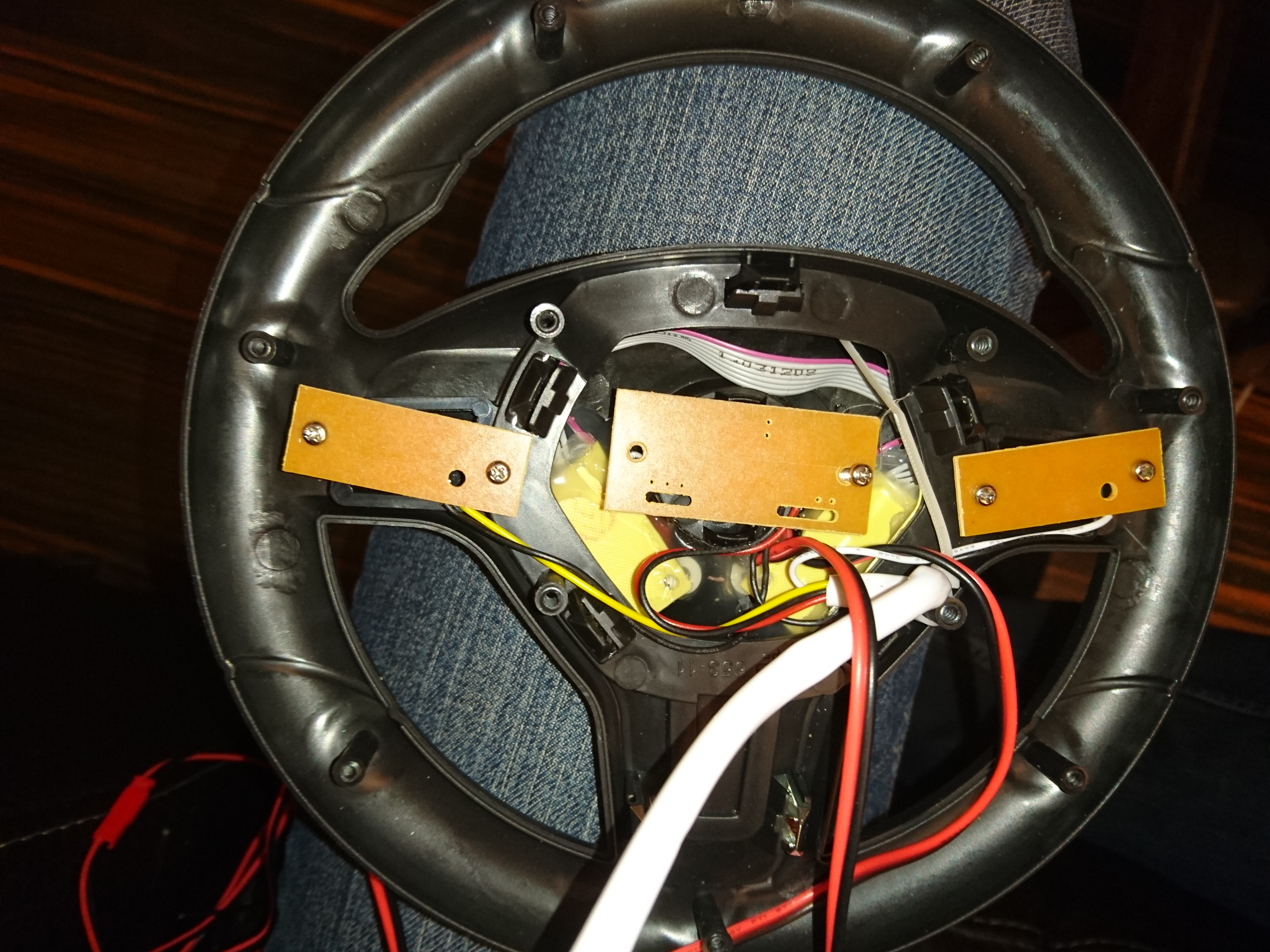
Now all the old electronics is mounted back into the steering-wheel.
Cable is threaded through the steering column, and the wheel is re-attached.
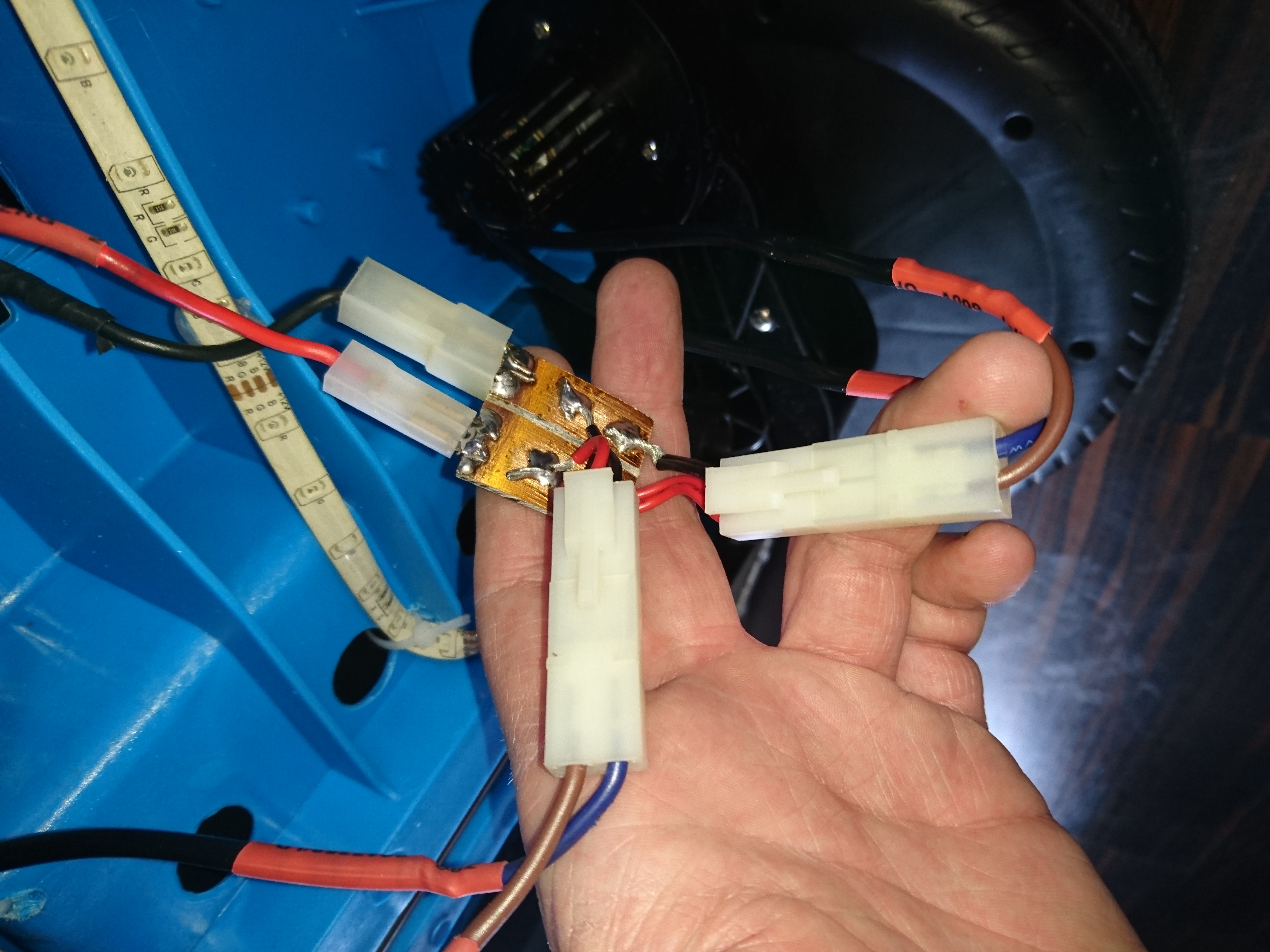
The motors!
Engines run in a serial connected fashion, but i hear people on the web slapping both one and two extra batteries on these motors, so with the new fat battery i decided i could afford to parallel-connect them instead.
I have two blocks like this. This one parallel connect the engines and the other serial-connects them, if i ever want to return it to that configuration.
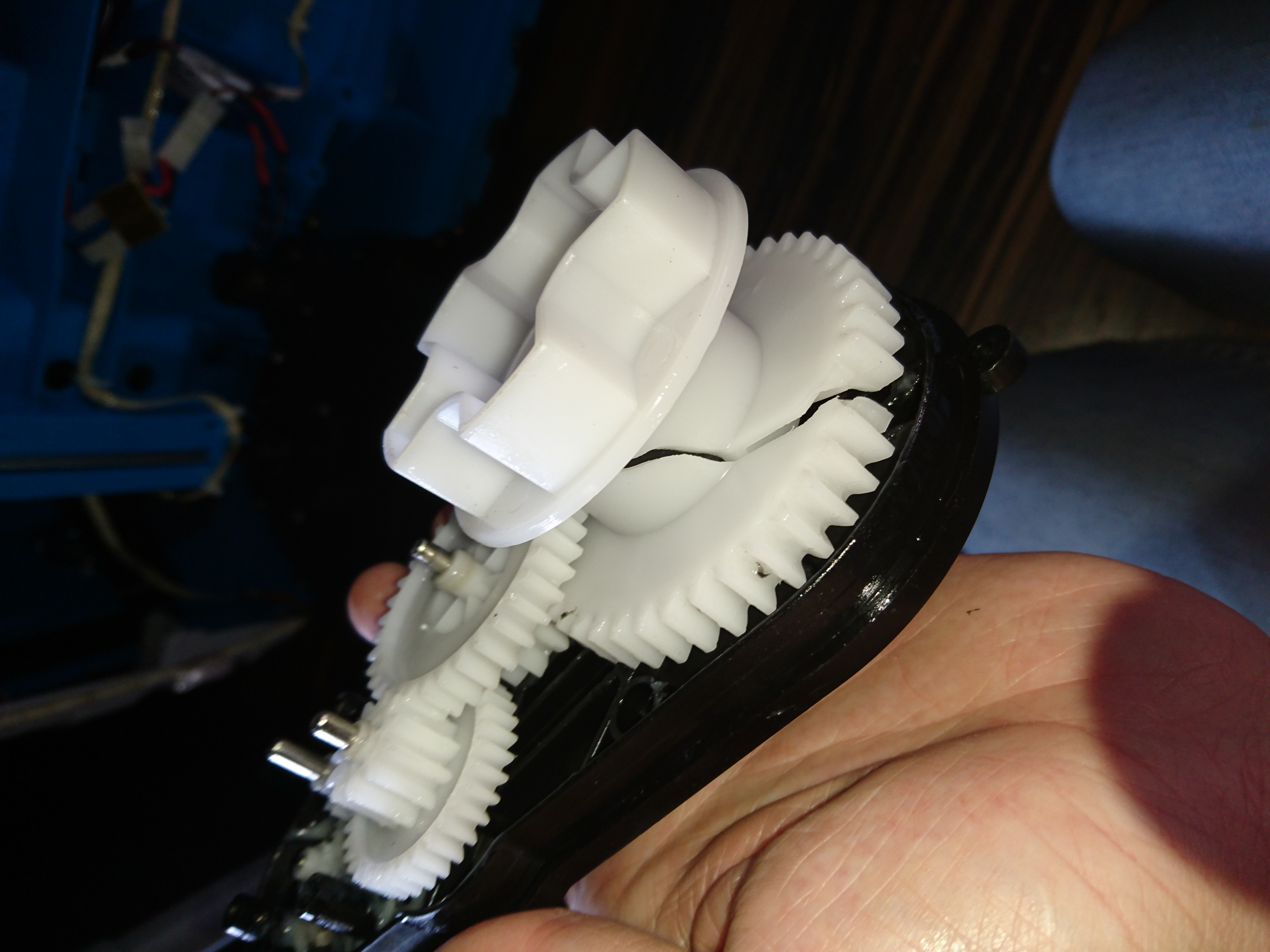
Disaster strikes!
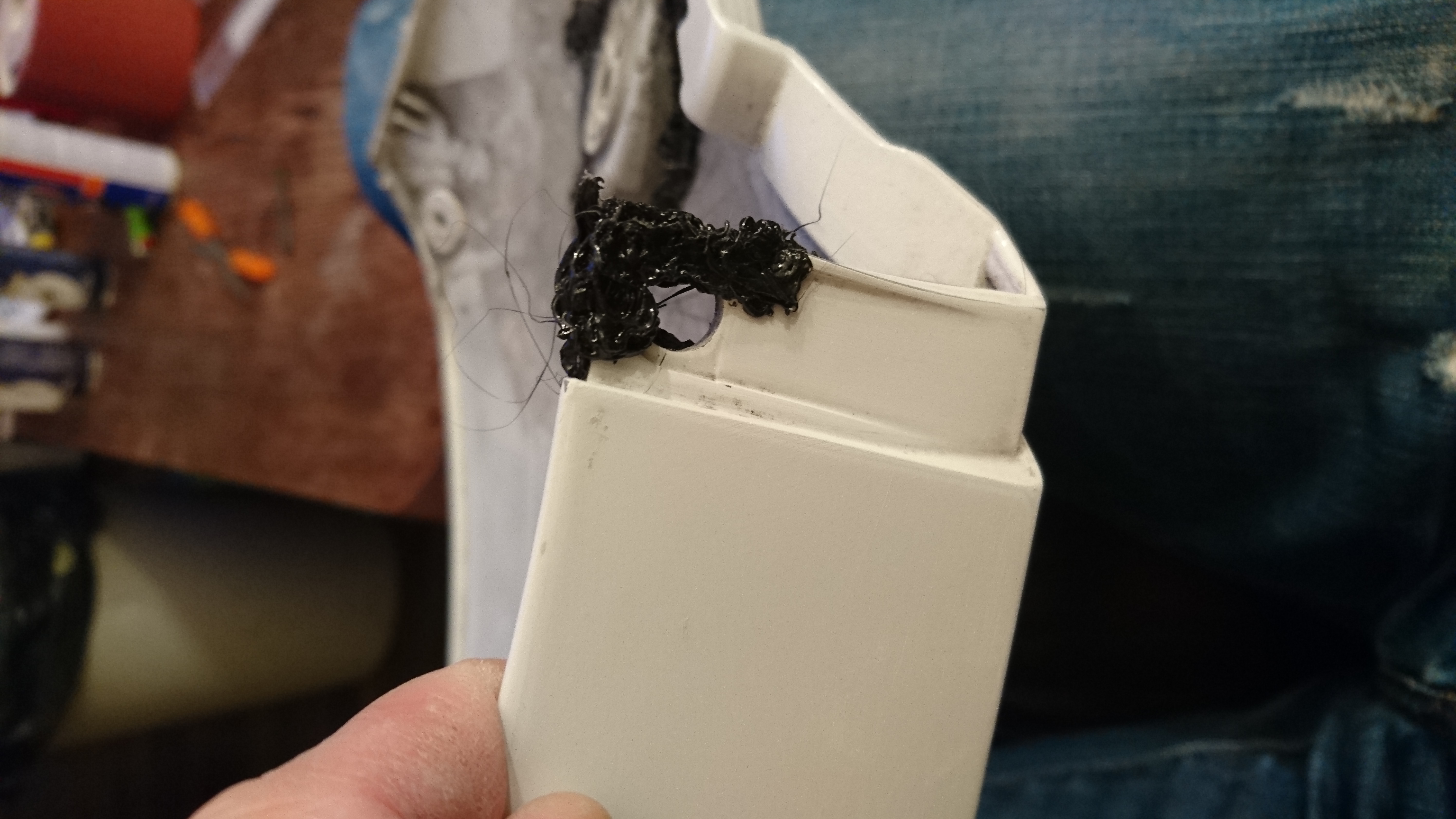
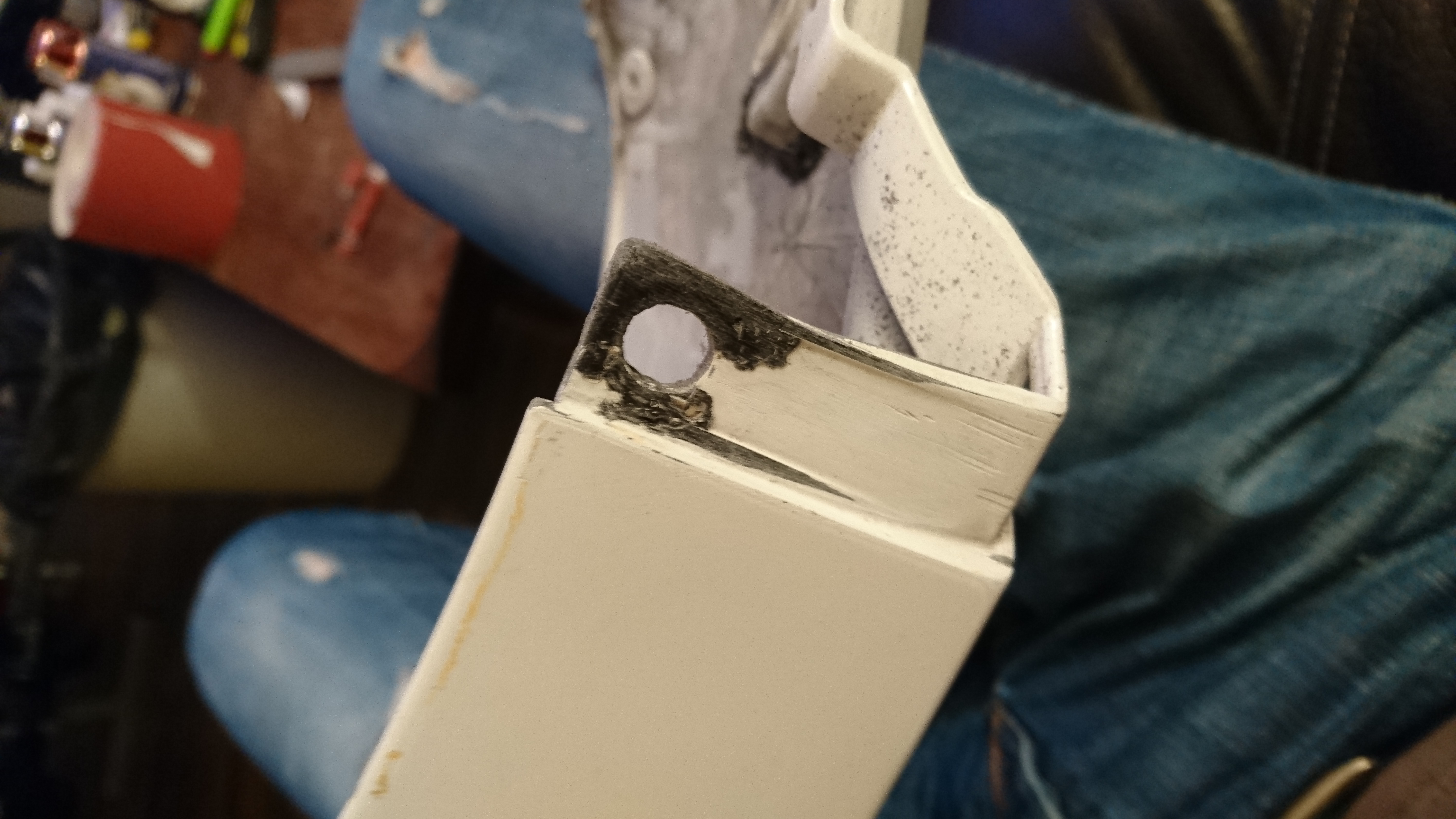
Unfortunately 12 volt, over a 40Amp ESC on a 12ah battery on the RS-390’s was i bit too much for the original design to deal with and one of the gearboxes tossed in the towel.
The accident struck as i was taking it for a test ride on the street by simply reversing the car and hitting full throttle.
I never expected the main cog to crack like this, maybe some of the smaller ones but not the largest..
This made me give up all hope on using those gearboxes for any larger or more powerful type 380/390 motors. I need something a bit beefier for transmission, or it will crumble just like this did very fast.
A new dawn
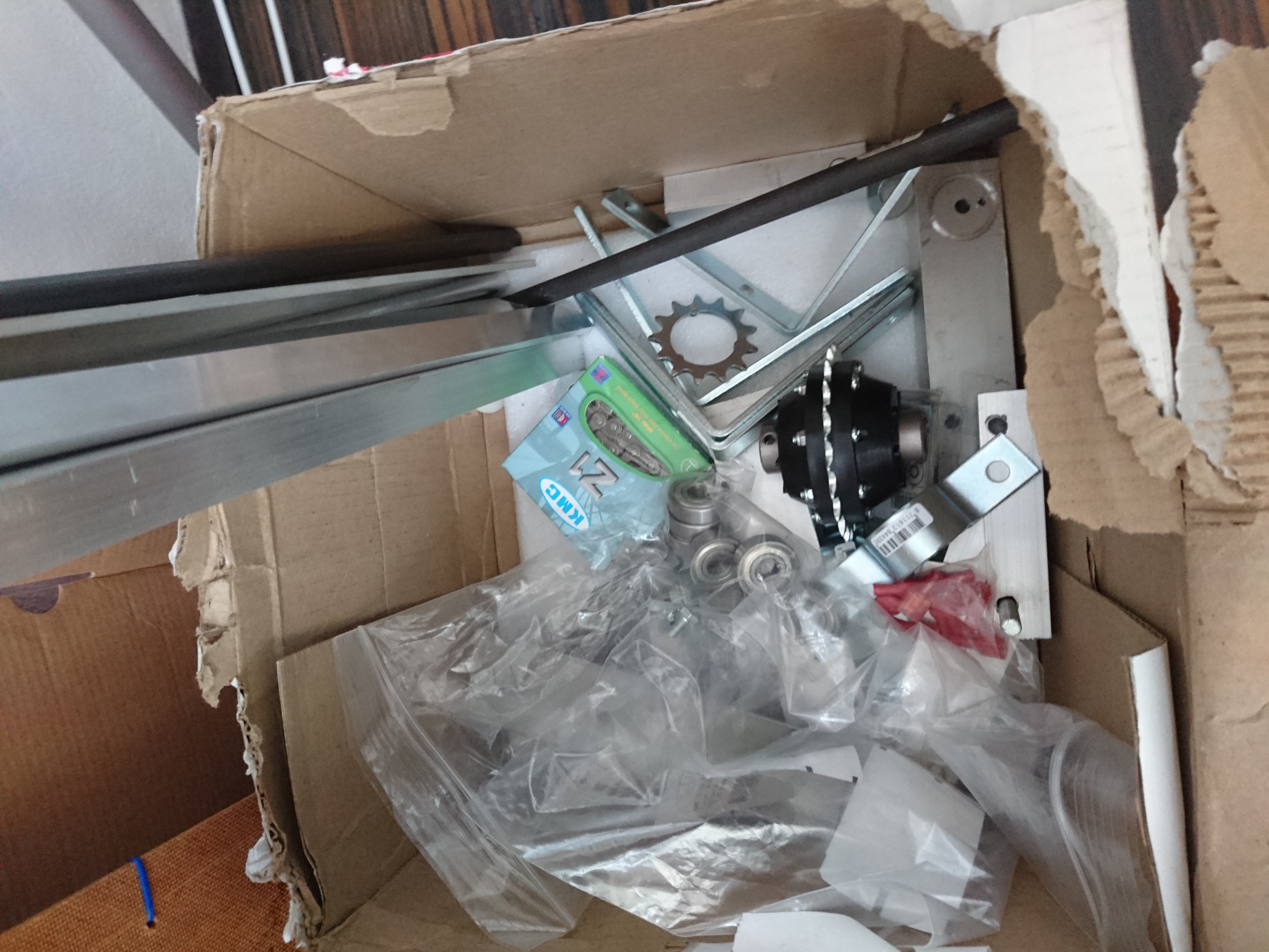
I went above and beyond the original motors when i bought a 48 volt 1000 watt motor of amazon. The motor is meant for a e-scooter and is 200 times stronger than the original engine so a frame will have to be built. I will follow the same practices you would if building a car. If possible with individual suspension and a rear differential to make sure it corners nice. The base will be widened about 100mm and lowered about 30mm to allow it to sit better on the ground.
Material is slowly collected, the engine, cardans and a rear differential has arrived, i am still waiting for the front disk-brakes and 40kg servos.
I also decided this build will need welding. For material i wish i could go aluminum but a lot of people keep advising against it, and my Argon gas is delayed 2 weeks, meaning i might for steel wishbones. I ordered a 200Amp TIG/MMA welding machine which should allow me to weld both stainless and carbon’ed steels. Additionally i had to rebuilt the main fuse-box in my house to be able to run it without burning my house down. As soon as my gas arrives i can start climbing that hill.
In the next part i will get a rear differential, suspension built and the motor mounted.
Suggestions and inspiration is very welcome. Current challenges:
I need wheels and have been looking for weeks with little avail.. They should be 300mm diameter, ~120mm wide, preferably with an aluminium hub and air-filled tires for weight-reduction. Any suggestions are welcome. I currently explored Golfcaddy’s, wheelbarrow, go karts and ATV/Quad.
Suspension. Should be 70mm(compressed)-125mm(decompressed) long and deal with 25kg each.
2017 has been super eventful year for me, not leaving much time to write here. As usual, work dominated most of my time and i added quite a few products to my CV.
Most importantly this year: I had a son, which in terms will be my biggest and most important programming project many years to come. Needless to say a lot of the hacks now aims at toys intended for him.
I attended SHA2017, where i started playing with PyQT5, went to a range of good talks which sparked interests in a bunch of new concepts like machine learning, that i am looking into more in 2018.
I bought a Kossel mini 3dprinter which i systematically broke every part on, redesigned and rebuilt. Once i am done upgrading the 3d printer, i decided i will build a 3d scanner too, so stay tuned.
I revamp the complete cooling system of my Honda CBR1000RR, crashed my Kawasaki Ninja 636, broke my hand, hacked the cast, ABS welded the fairing of the bike together again.
With all this 2017 have been packed with things to write about and the coming days i will start writing about these projects.
<DISCLAIMER> I started writing this post in 2015 but never finished it, mostly because i enjoy riding a motorbike a lot more than i enjoy spending hours spell-checking something almost no-one will read. Sorry once more, will get some new more relevant stuff here soon, but for now feel free to read this..</DISCLAIMER>
In a sense this entry don’t really belong at this blog as no actual hacking was ever needed so I am sharing this as more of a security advisory for someone that never decommission a server.
After a wet night in the bar with the guys I found a computer sticking out of a waste container on my way home. I noticed the IBM X-series logo which made me disregard that it was covered in an inch of snow and I dragged it home.
It turned out to be a X3200 tower, running a Xeon E3400 cpu at 1.8 ghz, 4 gb of ddr2 memory, 2 sata-mirrors. 80gb for OS, one 500gb mirror for data, by the look of it.
The hardware
After a proper drying I plugged it in. Power icon was blinking green but pushing the button did nothing. I measured the button using a multimeter, but the switch itself worked. I found a “Power On” jumper on the motherboard and once shorted the machine rev’ed up its fans but never let ACPI kick in to lower the RPM of the fans, nor initiating BIOS. Monitor indicated no VGA signal either.
I was fiddling with jumpers for quite some time, I reset the CMOS and noticed that when i moved back the jumper to Disabled that the box twitched to life. The monitor flickered up and the blue iconic X-series logo filled the screen, with a few beeps and warnings about the CMOS battery having low voltage it came back to life. Unfortunately I had no disk connected to the system at this point and it would take another 45 minutes before I succeeded to do it again. After hours of trying to streamline the process of getting it booted the recipe for success seems to be:
Use the Power ON jumper for 20 seconds. Pull the power-cord to the server. Enable CMOS-reset with the jumper on the motherboard. Put the power-cord back in. Leave the server for 20 minutes with the CMOS-reset ON. Then…. pull out the CMOS reset jumper :) BOOM! The server boots Windows 2003: A real man-OS!:
Not being a huge fan of spending 20 minutes on booting any machine I kept looking for something simpler. Trickling pin 2 and 3 on the WOL-connector on the network adapter did make the power-led on the motherboard flicker but once more didn’t start the machine up.
I never mentioned how restless I am as a person in this blog, but for people who know me that is a fact. What I did mention was that both OS and Data disks where both in a mirrored configuration, once this was confirmed in the BIOS, it allowed me to snatch one disk of each mirror to be able to see what was lurking on the sectors while waiting for the server to get ready for it’s next boot.
“This is Windows.. I know windows!”
I hooked up the OS-drive with a SATA-to-USB-dongle and mounted the NTFS partition on my linux-laptop. The 80gb drive was divided into 2 partitions. 21gb for OS and a 55gb labeled EXCHANGE. I was happy to see no attempt at encrypting (or destroying the drives for that matter) were made but I guess if I saw such attempts I would be even more curios to see what they tried to hide from me. I am far from an expert on Windows these days but it didn’t take long to locate the the email data-directory belonging to the email exchange server, that the partion-name indicated would be there.
TIL that e-mails are stored in clear-text in Exchange 2010.
Curious about who owned the machine before me I started reading mail after mail. A picture slowly dawned on me. Some kind of medical related, pedicure, new age thing, something? I was intrigued.
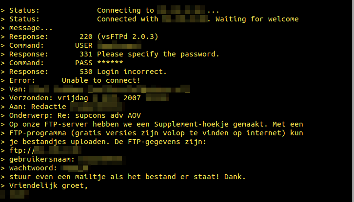
Using standard un*x tools like cat, grep and more I could see every email sent and received from 2007 to 2011. Just for the fuck of it I greped out 20 lines surrounding the word “Password” and “Wachtwoord” and piped it to two files.
Now, I understand a tiny non-IT company can mess up and send out clear-text password..
..but KPN is the stately owned phone-company in Holland, and should know better :)
Hosting companies don’t seem to mind keeping it simple.
I guess it’s up to their customer not to keep the same 6 character-passwords year after year. I am however convinced mijndomain.nl has changed practices on this topic anno 2015?
I want to point out that I never tried to use any of the passwords to verify if they worked or not as that would be highly illegal. Additionally some logins were to patient care systems, making it utterly unethical to touch. I did however google the companies, visited their homepages to get a greater idea of exactly what they did and how they connected to the company who’s server I stumbled into. Needless to say i read up on the company itself, which still exists.
Seeing many passwords never changed during the years and many were frequently reused between different systems, i feel safe to bet some of them still work. But I wasn’t really that curious about the passwords and continue exploring the rest of the emails. Who were these guys?
Slowly the picture of the prior residents cleared. They had their own little newsletter, were selling subscriptions, seemed to be holding courses, involved in Integrative medicine (Never heard of it before but I am a skeptic. A fast search through all mailboxes got me bored. Almost all of the emails in all the email-boxes was work-related, how boring of them. You can only read so many of someones emails before you need to do something else.
I started checking out the Data drive. It turns out this was not only the Exchange server in their tiny infrastructure. It also carried their Domain controller and roaming home folders. I searched the user home folders, starting with the Administrator account. I could not believe my eyes..
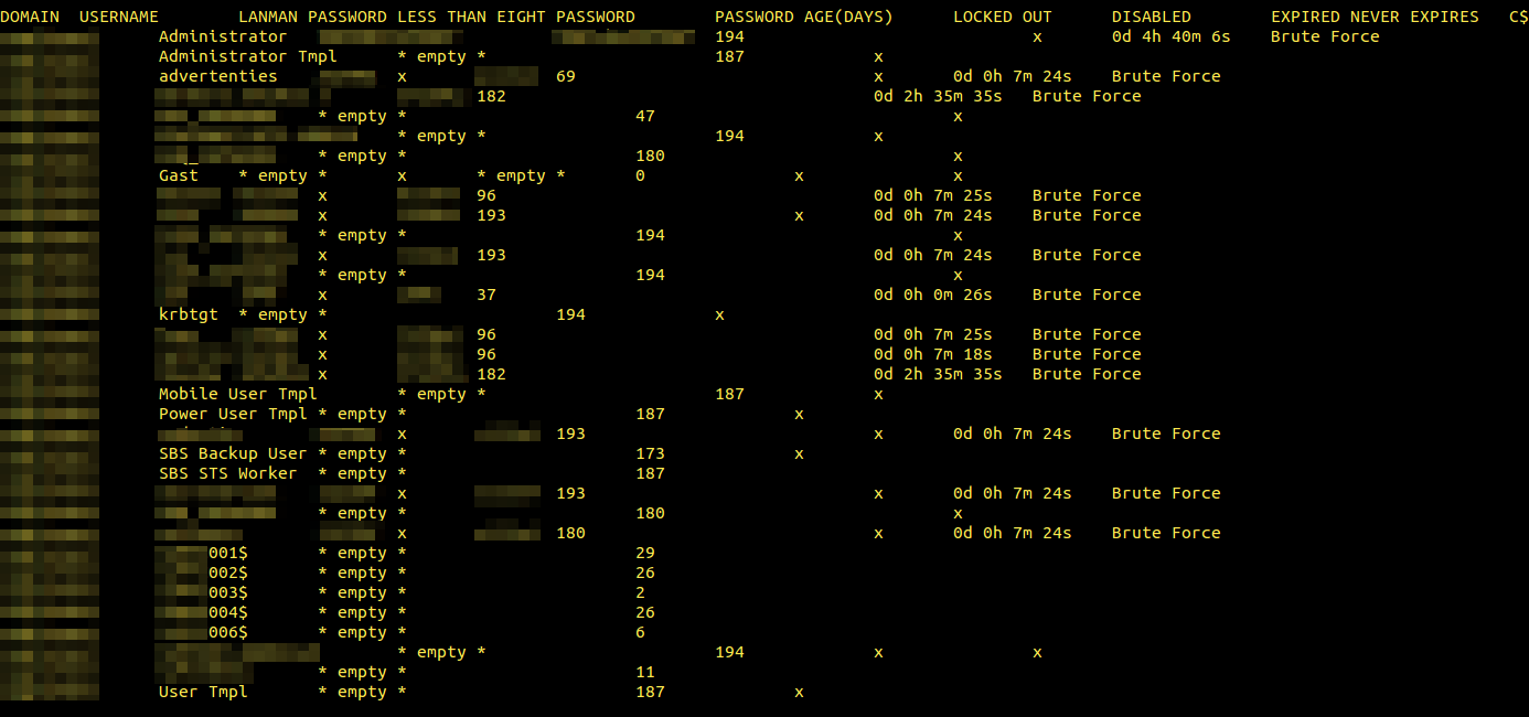
Someone already brute-forced the server and the result files were still there :)
Worth to mention is that it took 7m24s to brute-force the computer-knowing layout guy’s password, while it took 2h35m35s to crack he person I assume works in accounting.
Almost all passwords followed the same standard: X123Y4, where _123_4 never changes between users and the letters did to a certain degree. I can only assume these passwords were set by whomever delivered the system and never changed.
One user seemed to have changed his password but instead of setting a better password he went with a 4 digit only password, which was cracked in 26 seconds.
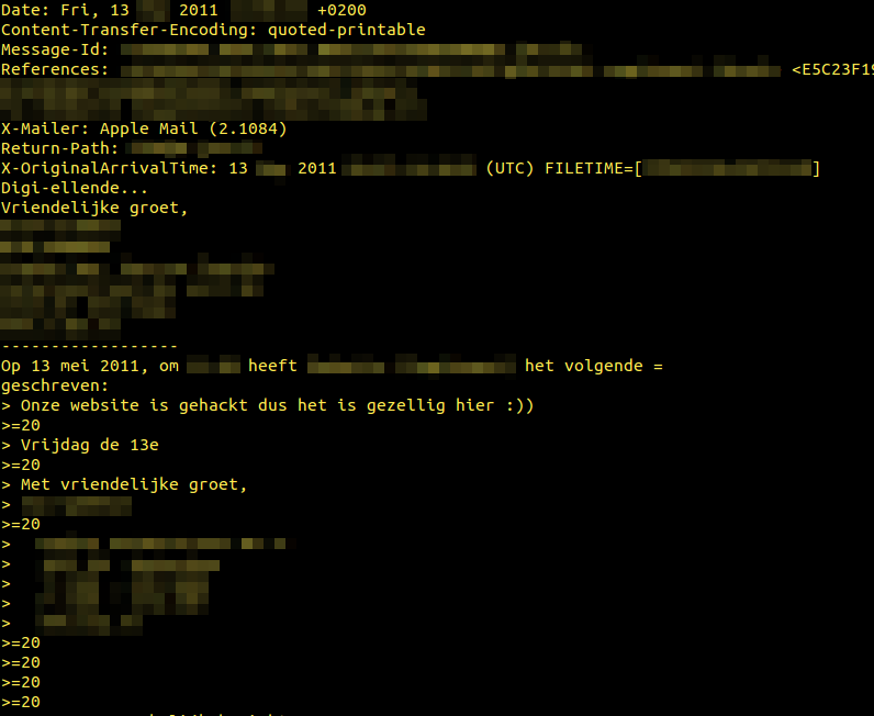
Initially i assumed it was the Administrator’s own pen-tests but looking through the mail again, it seemed they had been hacked around the same time this password file was created:
One guy seem to enjoy the peace it brought to the office and point out that it is Friday the 13th. Some external partner responds “Digi-missery”.
In the meantime the server booted up again
The server was finally booting up on two single disk mirrors. My eyes glittered in the LCD-light. I would finally get to hack something.. or.. well.. I had the passwords to all accounts already, so technically still no hacking. But i would at least get to enter a username and password and feel like a hacker. Nope, machine seemed to have a registry hack and automatically logged in as Administrator, but something hung it after that. As i didn’t want it to start connecting out on the internet i just hooked it in to a switch without uplink.
I have to say I was a bit surprised to find the brute-forced password file, but not as surprised as I was about to become. Turn out this machine also hosted several windows shares.
One was most likely used by their HR, as i could find ALL information about people working there, like digital copies of their contracts and dismissals.
Another share contained a lot of access databases. Their complete customer-database, sales records, lists of prospect customers and tons of PDF-material about their products.
With the data i had at this point, i could map the whole company up on a time-line, seeing who started when, what they got paid, when they left. I could build a visual picture of who emailed who, which seller caught the big fish and who was just complaining about work while slacking. With almost 10GB of email, 500GB of data and no real idea of where I wanted to go out of it, this blog-post got hanging mid-air. It would take a year to go through it all. And most of it way to fucking boring to plow through.
I kept looking and found pictures from a few events their company participated in. Some of the pictures were named after who they depicted, allowing me to put a face on most of the names from emails i had been reading. It almost felt like i knew the people at this point. I was about to get way closer than i wished for.
I explored the the data-drive and found a backup windows share. Turns out this server was also used by some of the people to back up their laptops, and some of them were very.. blunt.
One of the sales guys, which i recognized from pictures i found from a kickoff he went to was obviously gay. I don’t claim to be able to spot a gay guy, nor do i judge anyone being gay but this guy had tons of pictures of him and a friend fucking a tiny Asian man making me pretty sure this was the case with this guy. Among the data he traveled with (and cared enough to backup) was GB’s off piss-porn.
I wanted to finish up this post a while back, but as i mentioned, I had NO IDEA of what to do with this. Obviously i would never attempt to use it against the company or any of their employees, but the next guy to find this might not be as friendly as I am.
Bits of advise, anyone?
No matter what you Think is on a computer you are getting rid off, small pieces of your life’s puzzle are stored on that machine. May it be in your internet-cache, in your cookies or from RAM in a swapfile. Someone with the right motivation or amount of interest will be able to scavenge it and use it against you.
If you ever toss away anything with a NAND-circuit (like a broken cellphone that contained naked pictures of your gf), unscrew/drill out the screws and use the a car battery charge to short every circuit on the board, making sure who ever tries to retrieve the data, gets a run for his money.
If you ever toss a PC with a harddrive, remove the drive, smash it to pieces with a hammer or drill right through it a few time. It only takes a few minutes, and you know for sure you are safe from 99.9% of people as curious as me.
If you are decommissioning a combined mail-server, file-server, piss-porn-repository, containing all your financial statements, all your customer information, every edge you have on your competition: For the love of Science, make sure no-one can just pick it up and just power it on.
I have always loved the VX1000-series of video cameras from Sony. Released in 1995 at a price of $3500, this camera revolutionized what Sony calls the “prosumer” customer segment, being the first DV-camera using Sony 3CCD color-processing and firewire interface. To this day, the VX1000 has a huge active community and a refurbished camera can still bring up towards 800 euros, something you rarely see with 19 year old electronics.
A friend of mine was lucky finding one of these tossed out on the streets of Amsterdam a half year back and as soon as i saw it i wanted it. It had no charger but he knew what he got his hands on and figured he could probably get it working.
Some time passed and my friend realized he would not get around to fixing it so i figured i could give it a try and bought it cheap.
First thing i checked was the battery, which was dead. At 7.4 volts, i had nothing that could charge it but building chargers and batteries gets boring at some point and that point was reached for me :). For 49 euros i got a pirated battery and charger:
I charged the battery and inserted it and a tape in the camera. It sucked in the tape and i recorder a minute.. At this point i wanted to play back what i recorded to see that it was working. I was a bit confused as i could not see any controls such as play, stop, rewind and so forth anywhere :)
I downloaded the user manual, checked the playback part and tried to follow the instructions. “Press play” was the last step. I could still not see a “Play” button anywhere. I verified that i was reading the right manual, and i was. “What a fuck?!”.
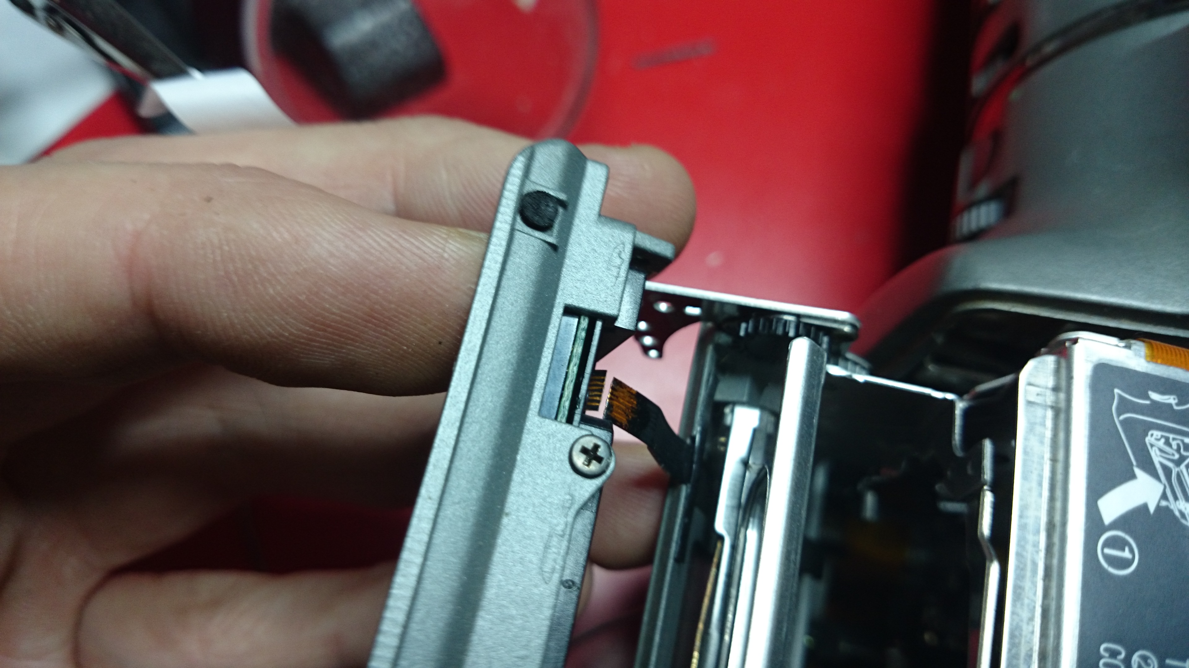
Googling the camera model, they all looked the same to me. Where the hell was the play, rewind and so forth?!! Then i stumbled over this picture:
Turns out these are back-lit by leds and can not be seen when the camera is powered off. That’s when i discovered this broken flex-ribbon:
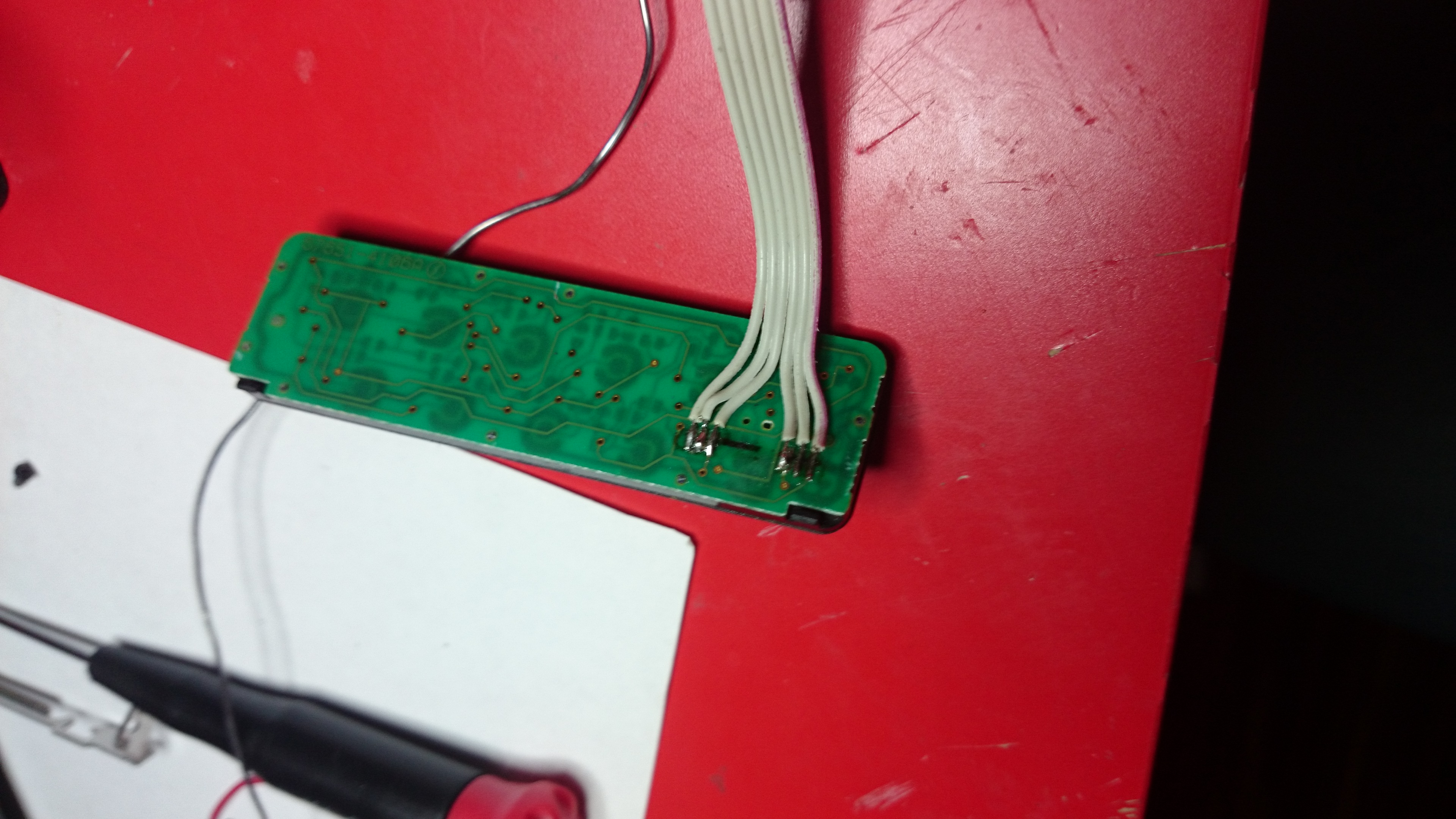
This was gonna be tricky.. I had attempted to solder onto flex-ribbons before but always failed miserably. I checked youtube and found this guy in the same situation. His solution was to scrape the plastic off, scrape the copper until it was really shinny, put a tiny amount of tin on the connector and solder on a tiny copper to each missing link. His was missing 4 and he had all the space in the world while mine had 6 and was in the worst thinkable place. Luckily the hatch hiding the tape can be opened while both filming and replaying content allowing me to make a ugly fix to verify that this was the only problem.
I unscrewed the button panel and cut of 10 plastic pieces that held the controller together and unsoldered the tiny piece of flex-ribbon left on the board. I soldered a flat-cable that i took out of a IDE-cable as a replacement for the broken flex-ribbon. On this side it was quite easy to fit the wiring as there was some space left, once pieces of the plastic was grinded away with a dremel. I resealed the panel with 2 component epoxy-glue and continue to getting ready to attach the other end of these 6 cables.
Like i said, soldering something onto a flex-ribbon is not a simple task and having failed before i refused to start doing this on the camera until i mastered it. Luckily i still had the tiny piece of flex-ribbon left from the control. It was only 8mm long but big enough for me to get some practice. As i felt i had control of it, i moved over and started working on the camera for real. Two down, 4 to go:
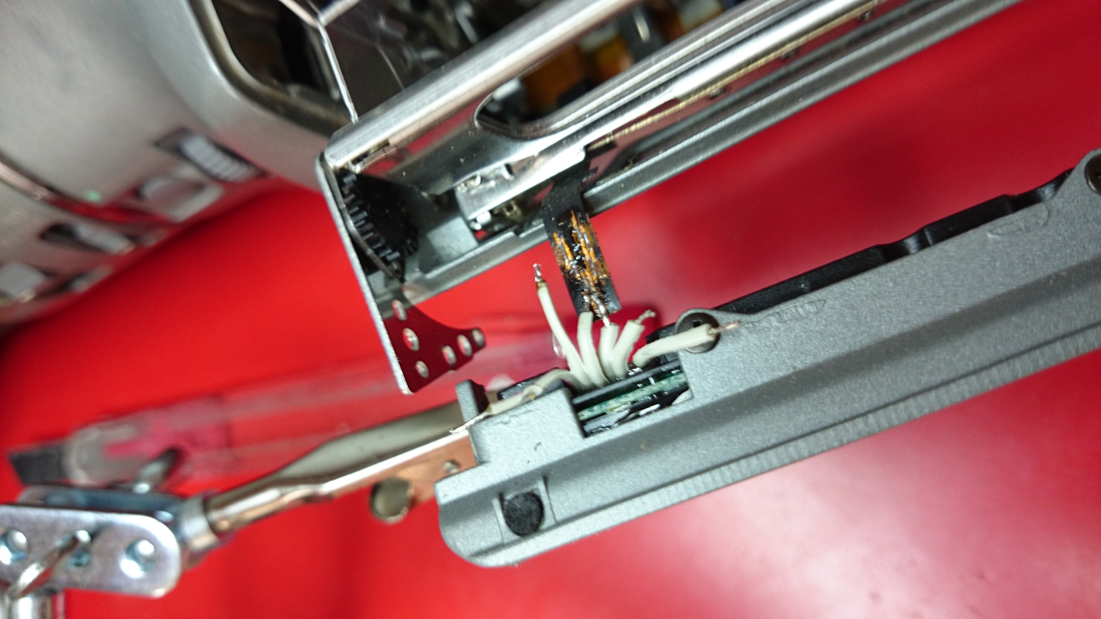
By placing the soldering’s like a step-stair along the lanes, even these “thick” cables could be connected right on the lanes without short-circuiting any of them. I would lie if i said this was easy and that i did not curse during this whole exhausting 1 hour procedure.
If you are doing something similar and and need to solder on to a flex ribbon my best advise is avoid breathing. Place the replacement wire using a scalpel and once you think you got it where it needs to be, hold your breath and just touch the cable with the solder-iron for a fraction of a second. Make sure you have space around you while working and that cables aren’t being tangled up and potentially destroying your work as you lean out. A good magnifying glass is almost a must. Make sure you don’t support the weight of any parts on these tiny solder-points as it will rip of and potentially destroy more than you just fixed. Additionally take time to verify that every connector is soldered firm and does not cross-connect to other lanes using a multimeter, before connecting the battery/power.
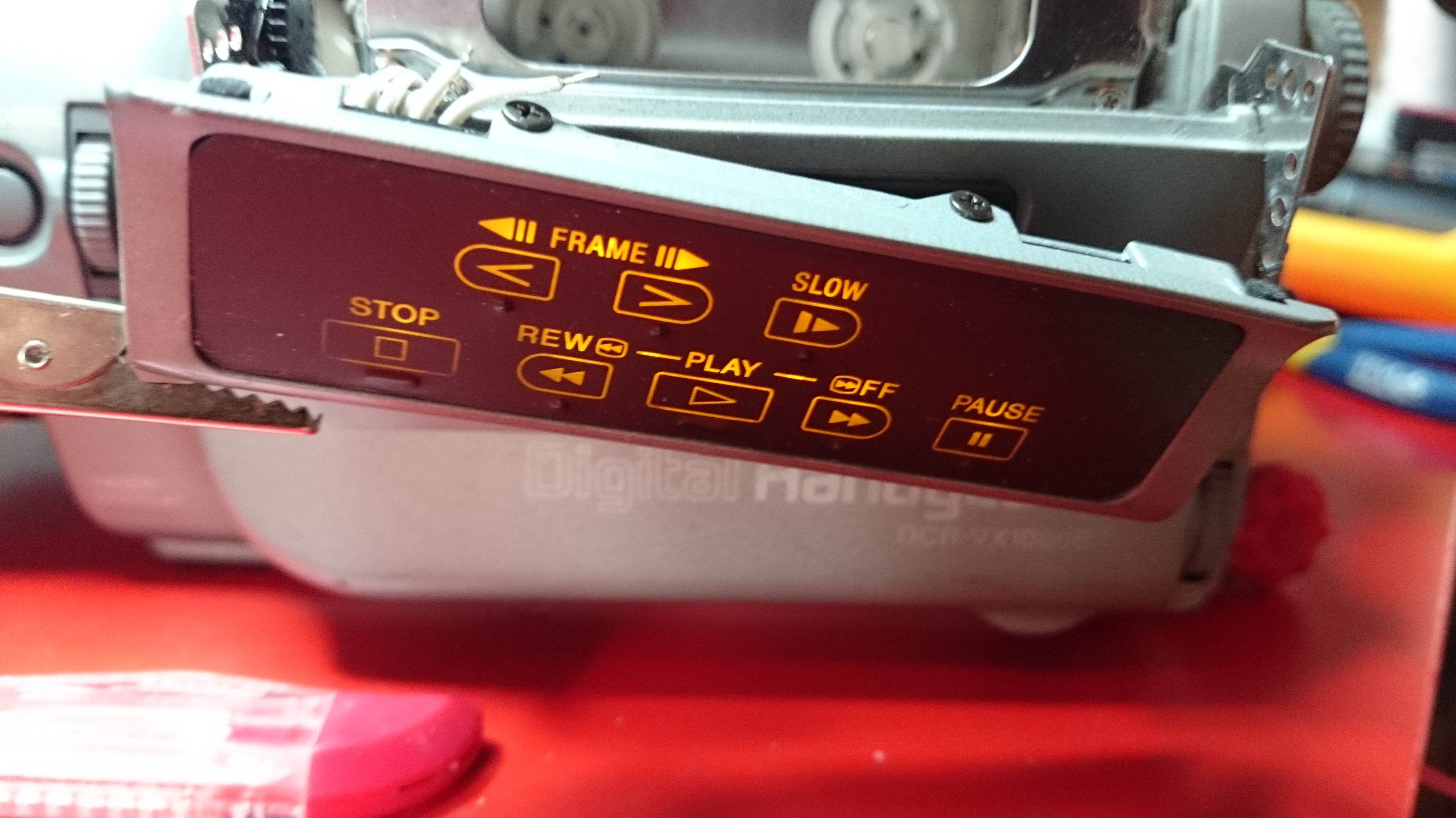
About half an hour into the process the plus and gnd is connected, allowing the LED’s to once more shine:
After all 6 wires are back, i re-mounted the hatch and did a little measurements to verify all was good. All but one line worked but it didn’t take long to find the faulty connection.
Don’t let my cats lack of cooperation undermine anything i have just written, she just hates cameras:
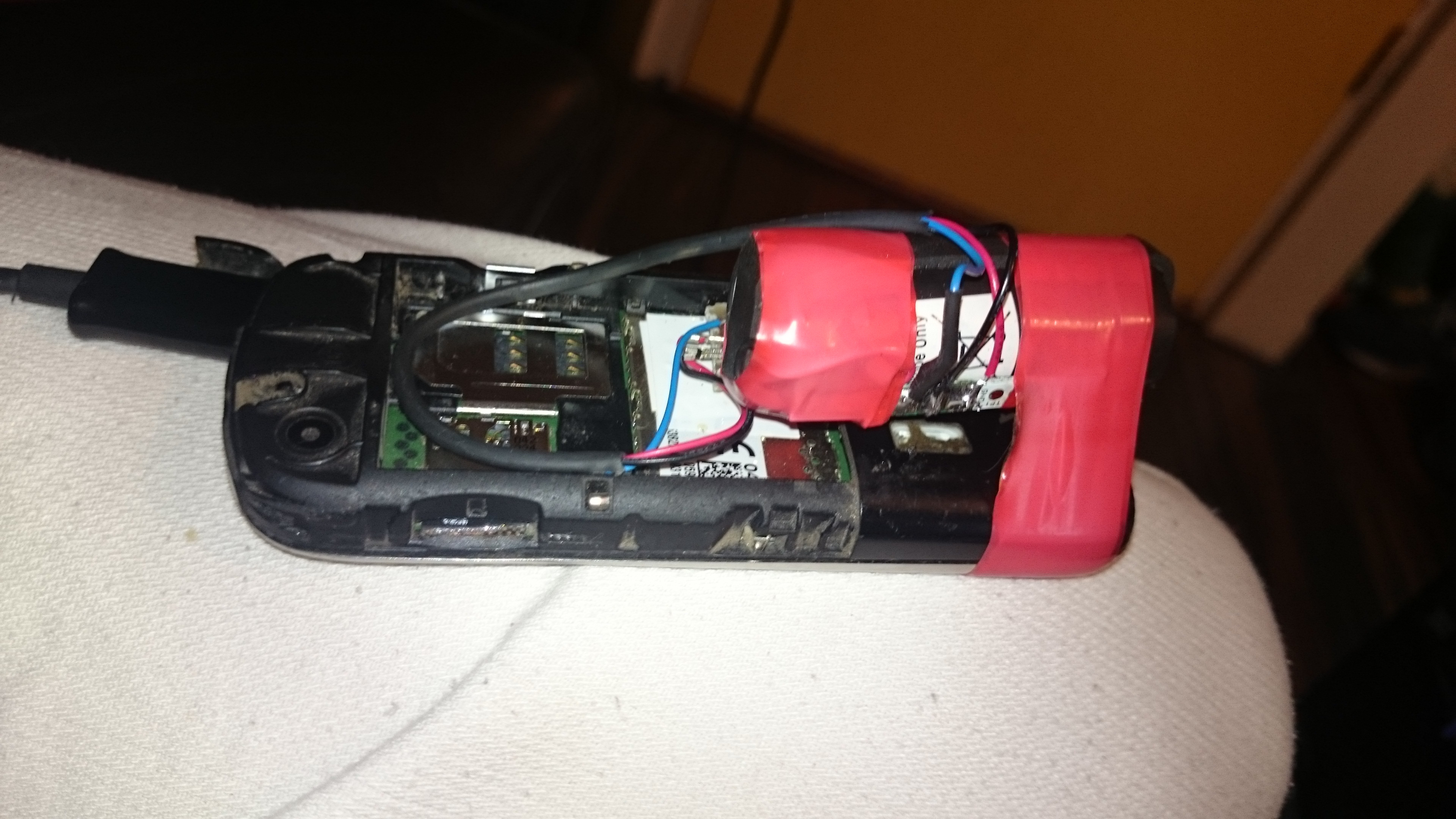
A good friend of me approached me 2 months back with his broken Nokia cell-phone, that all of a sudden died on him.. Number, pictures and messages were stored in the phone, leaving him without all his contacts.
I figured i could just have a look if it was something simple and if so, get it alive again to be able to back it all up. Once home i first tested a regular micro-usb cable but i did not see any led blink or indicate that charging was taking place. Measuring the battery it was totally flat but lacking means of charging it i told him that i didn’t get very far. Since that the phone has been laying around, doing no good to no one.
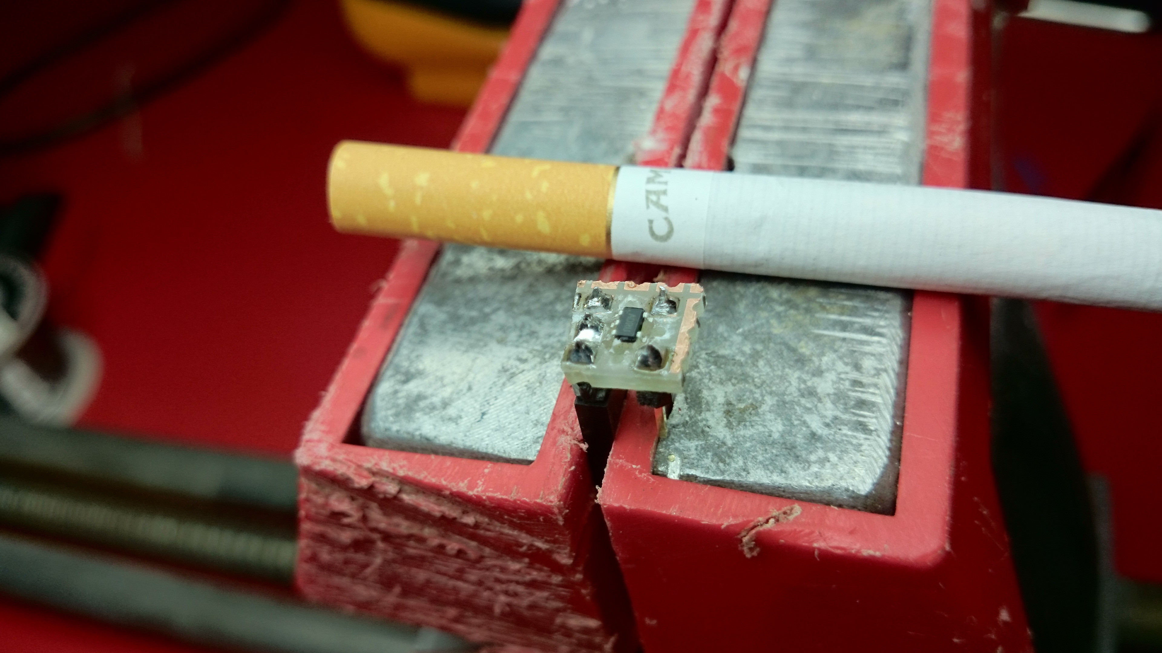
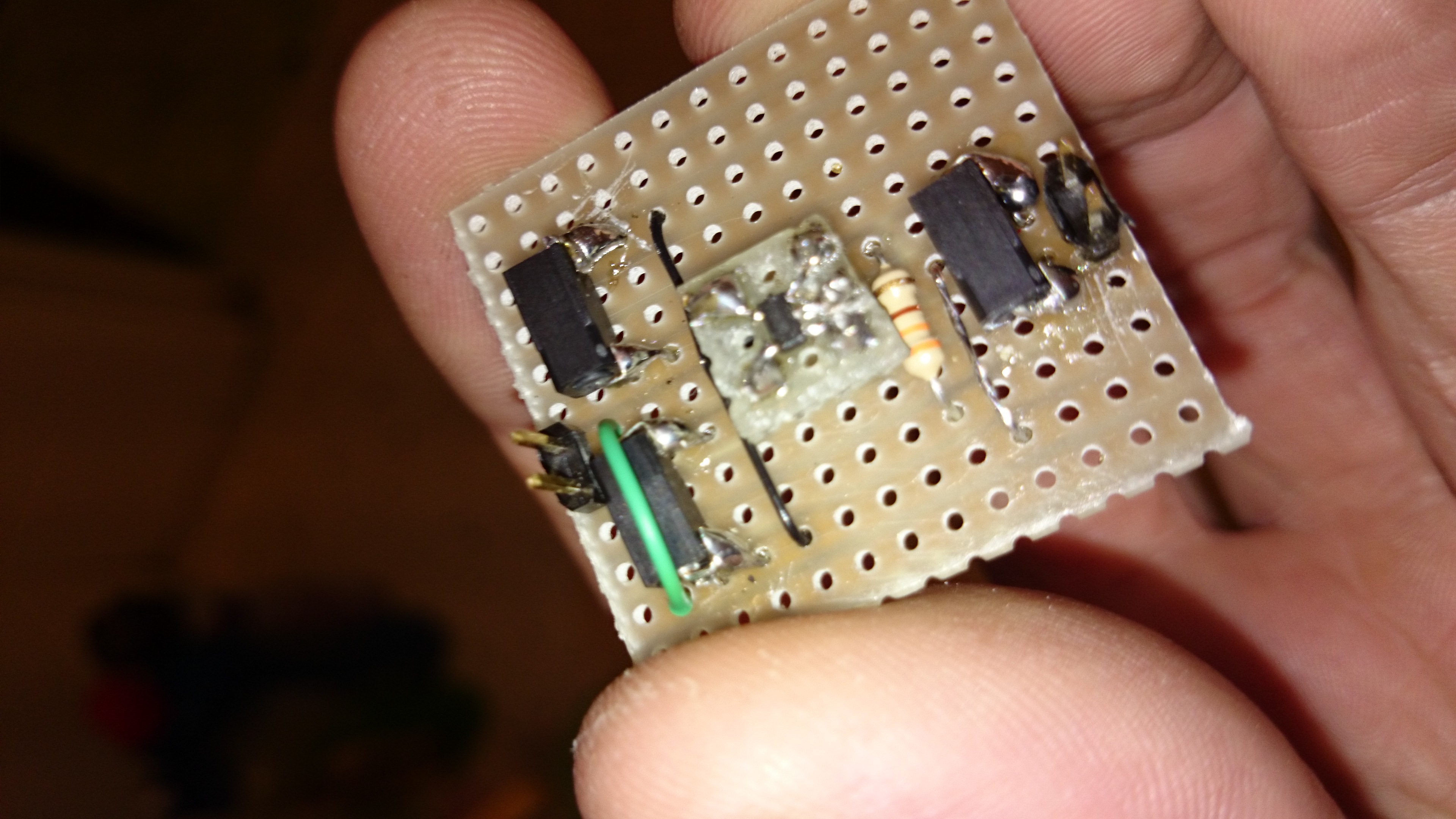
As i finished of the video camera charger the other day, i still had some max1555’s li-ion charger circuits at my disposal and figured i could build a second charger and see if i could get some life in the battery circumventing the phones own charging system. Since this would not be a permanent install i figured i would build something that could be reused, that had clear test-points and that could easily be connected to whatever cell i needed to charge. As space was not an issue i mounted the MAX1555 on a separate board (cigarette for scale, the MAX1555 is a non-smoking IC)
And then continues to lead out the tiny legs of the MAX1555 to the board. This board was added on top of the next circuit board using basically almost the same schematic as for the video-camera in the earlier article.
The battery belonging to the phone turned out not to accept charge, and in retrospect i find out the phone broke when he tried to charge it with a 220 volt charger in New York (110 volts ftw!).
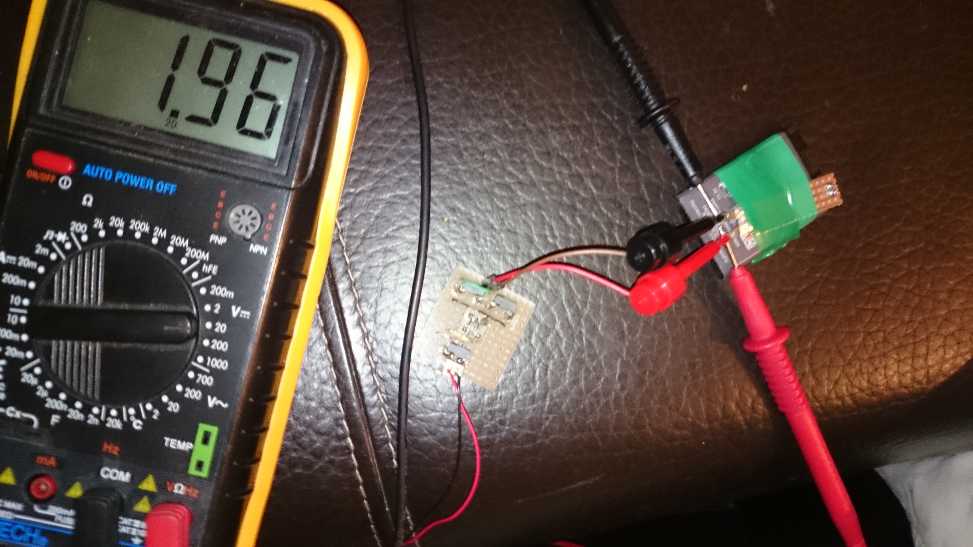
This explained a lot. I took old nokia li-ion battery, hooked up the charger and the multimeter to see that the charger was working and the cell accepted the load:
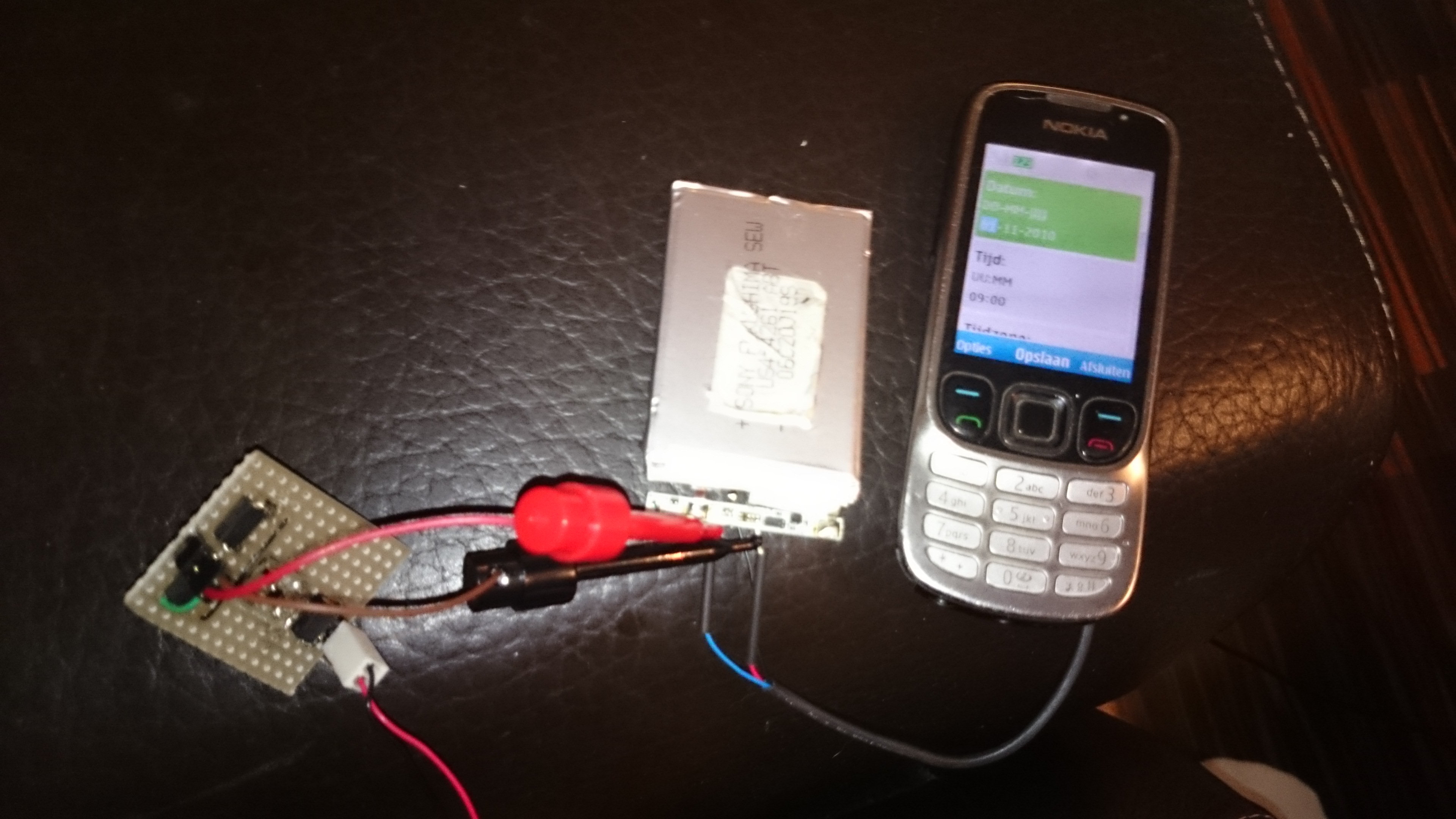
Turns out this old battery also had done it’s fair share of heavy lifting, and i had to dismiss it. Next battery in line was another Nokia battery from one of it’s first smart-phones. This battery worked straight off, and as i reached the magic 3.7 volts, i connected the battery to the phone and pressed the power-button, VOILA!
I called Mat to inform him the phone was alive again, who was very happy but this celebration lasted short, as the aluminium connector from the battery broke off, and no matter what i tried, i could not reconnect it. Having ran out of Lithium-Ion batteries i was stuck with Lithium-Polymer batteries. I desoldered the battery controller seen under the accumulator in the picture above, i soldered it to the LiPo cell instead resulting in a working but franken-phone seen here:
It’s not beautiful, but it is working and all contacts and sms are once more safe. Yet another happy customer :)
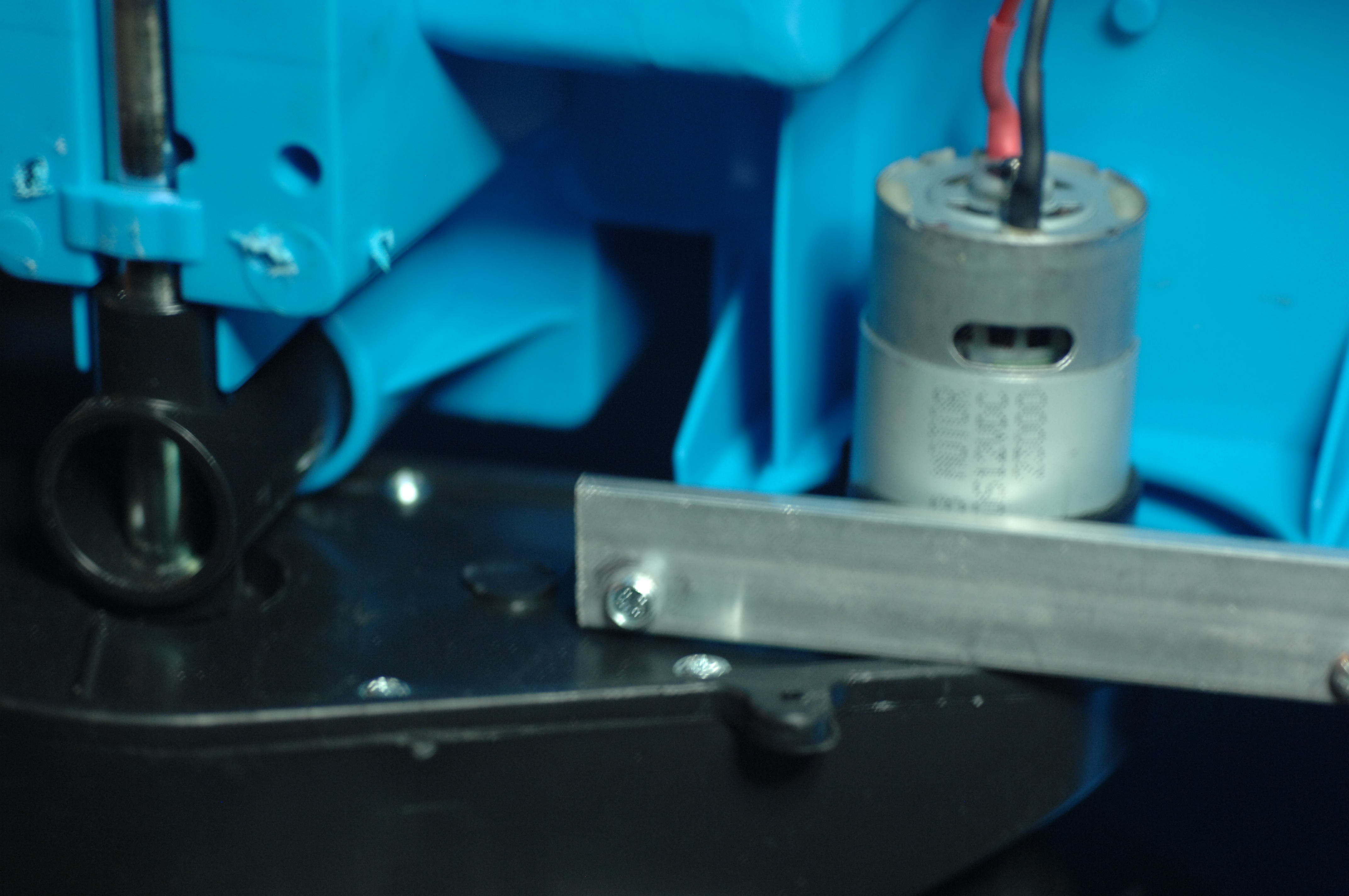 These are the RS-550 12VDC doing 23.000 rpm.
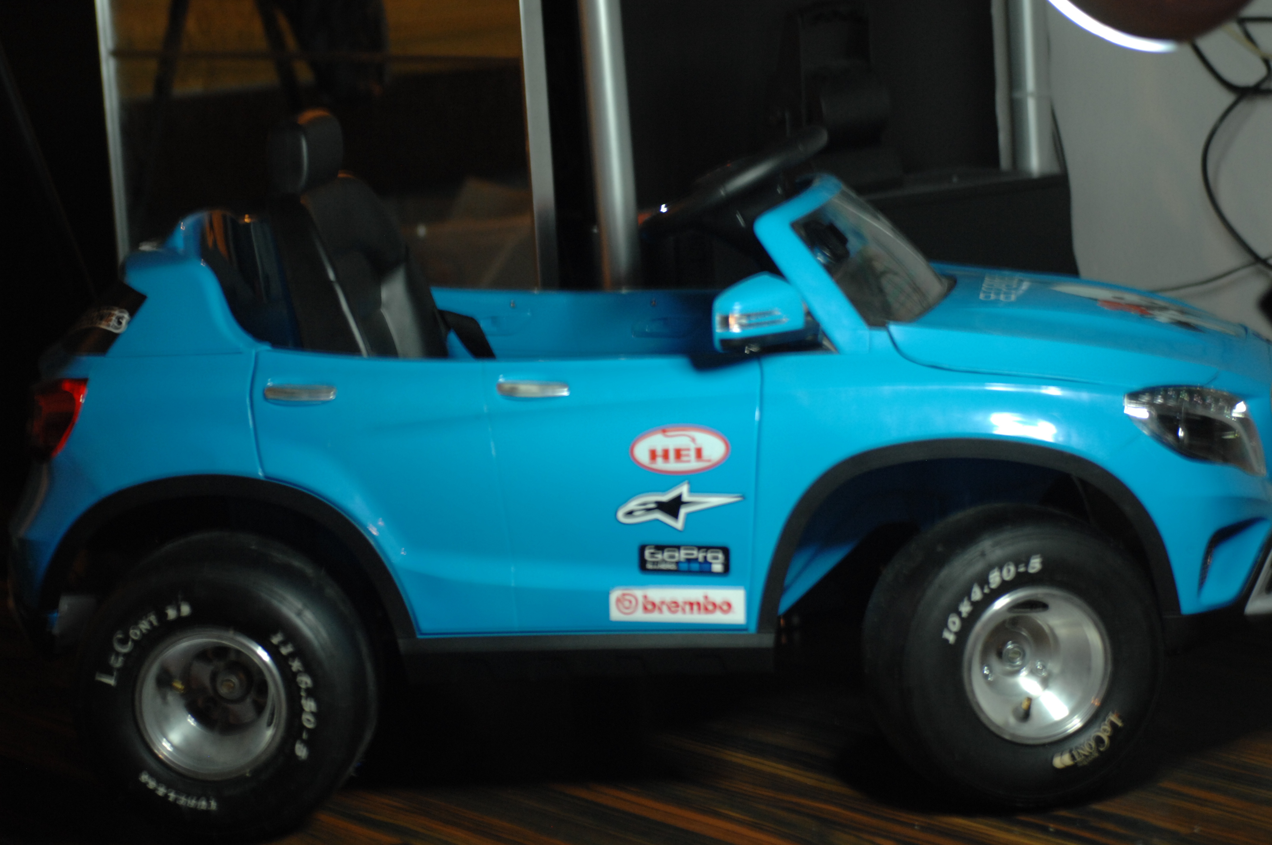
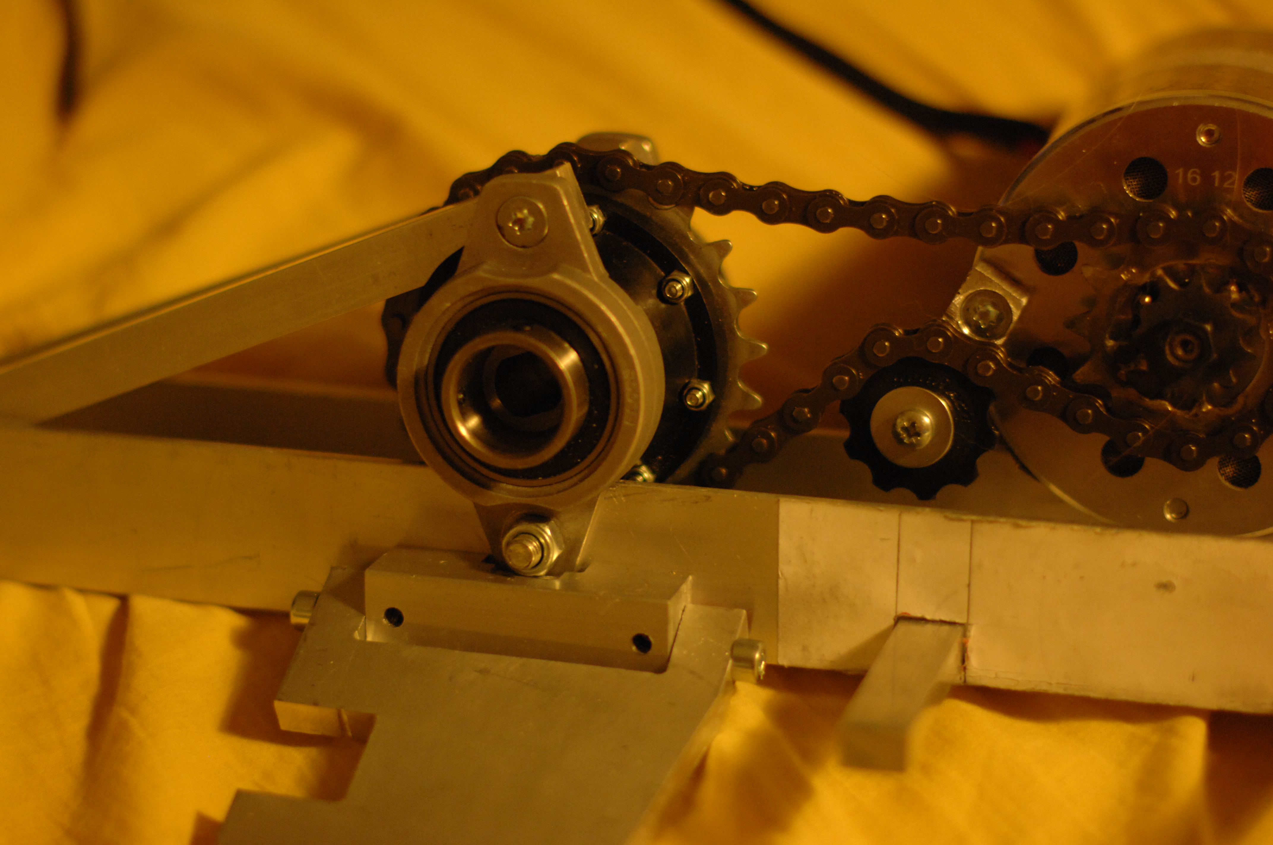 Rear differential, bearings, chain, chain-tentioner, electric motor and the lower control arm mounted. Battery box will be mounted on the opposite side to the motor to balance out the weight.
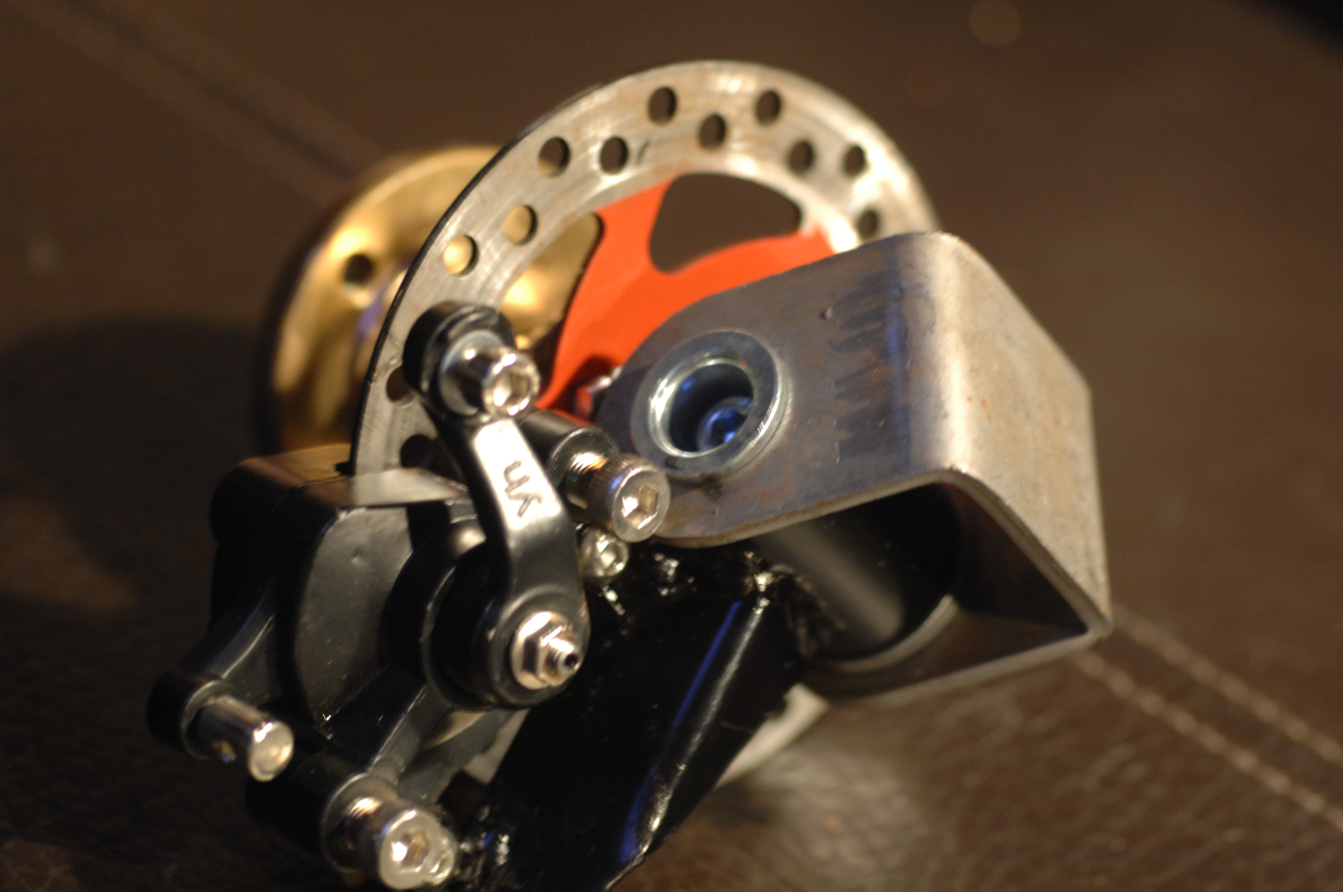
 s/class/scsi_host/host0/scan