I have always loved the VX1000-series of video cameras from Sony. Released in 1995 at a price of $3500, this camera revolutionized what Sony calls the “prosumer” customer segment, being the first DV-camera using Sony 3CCD color-processing and firewire interface. To this day, the VX1000 has a huge active community and a refurbished camera can still bring up towards 800 euros, something you rarely see with 19 year old electronics.

A friend of mine was lucky finding one of these tossed out on the streets of Amsterdam a half year back and as soon as i saw it i wanted it. It had no charger but he knew what he got his hands on and figured he could probably get it working.
Some time passed and my friend realized he would not get around to fixing it so i figured i could give it a try and bought it cheap.
First thing i checked was the battery, which was dead. At 7.4 volts, i had nothing that could charge it but building chargers and batteries gets boring at some point and that point was reached for me :). For 49 euros i got a pirated battery and charger:
I charged the battery and inserted it and a tape in the camera. It sucked in the tape and i recorder a minute.. At this point i wanted to play back what i recorded to see that it was working. I was a bit confused as i could not see any controls such as play, stop, rewind and so forth anywhere :)
I downloaded the user manual, checked the playback part and tried to follow the instructions. “Press play” was the last step. I could still not see a “Play” button anywhere. I verified that i was reading the right manual, and i was. “What a fuck?!”.
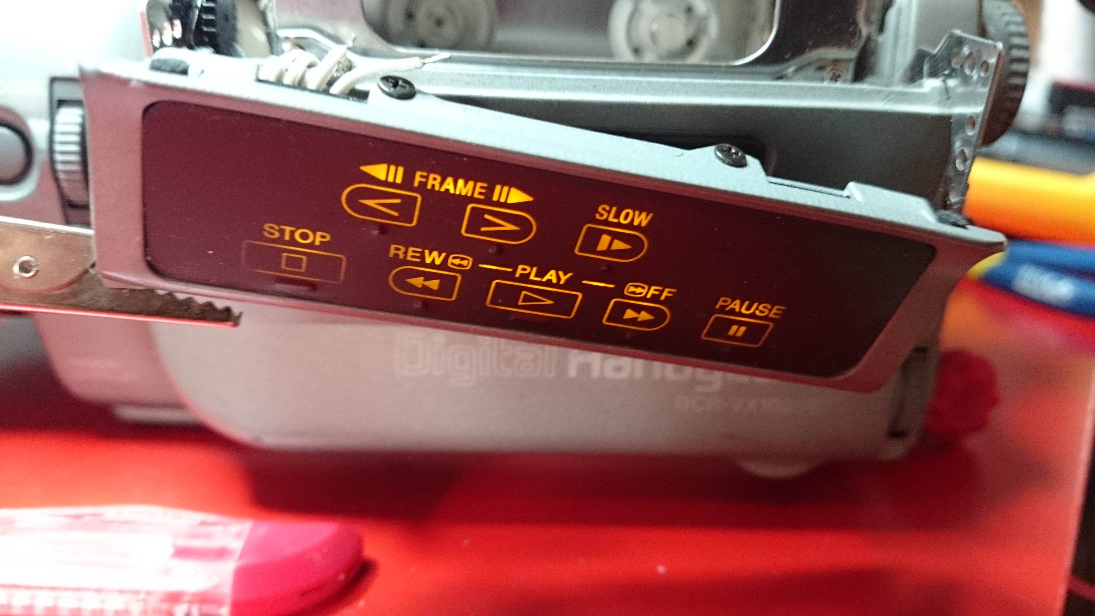
Googling the camera model, they all looked the same to me. Where the hell was the play, rewind and so forth?!! Then i stumbled over this picture:
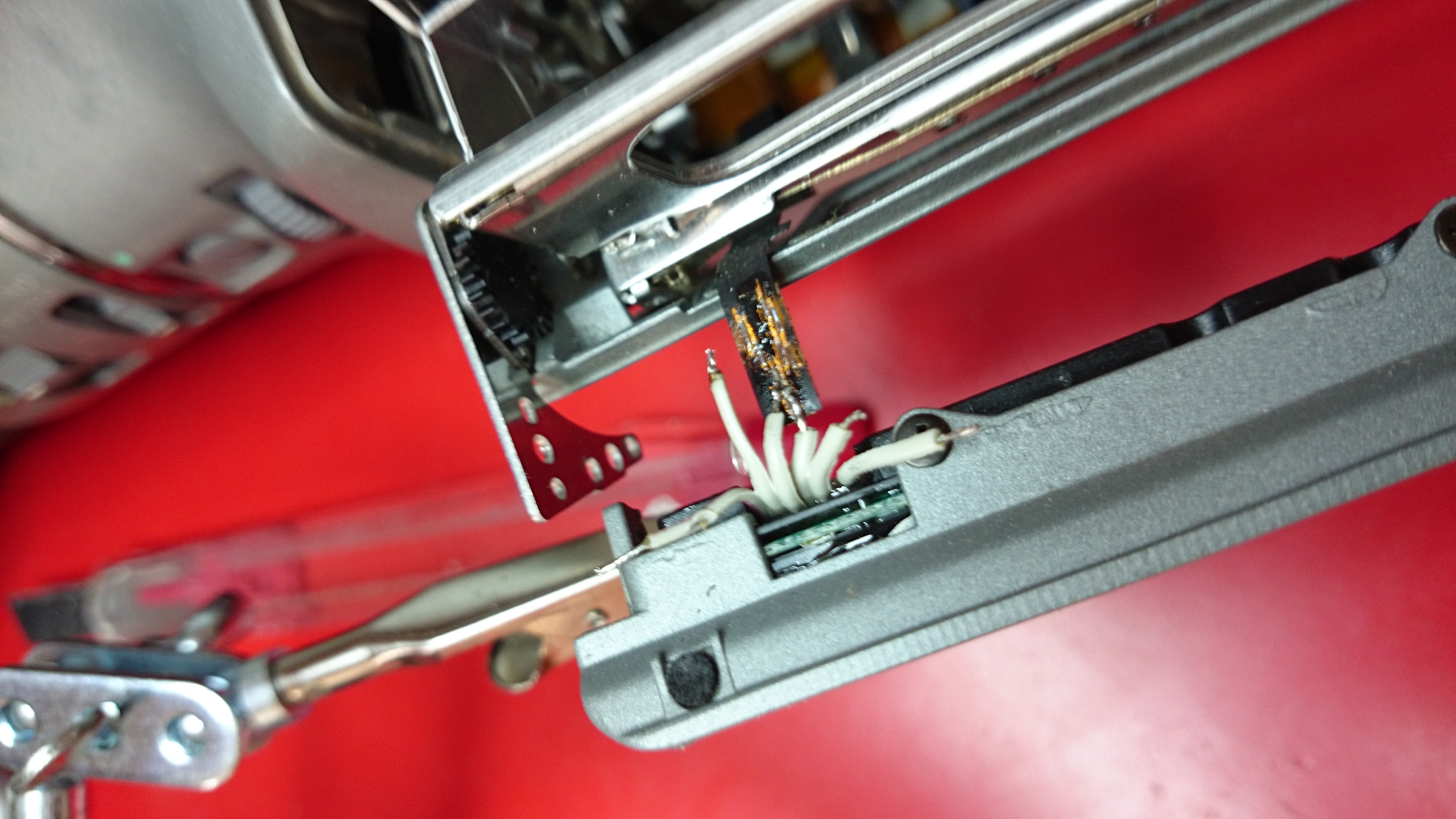
Turns out these are back-lit by leds and can not be seen when the camera is powered off. That’s when i discovered this broken flex-ribbon:
This was gonna be tricky.. I had attempted to solder onto flex-ribbons before but always failed miserably. I checked youtube and found this guy in the same situation. His solution was to scrape the plastic off, scrape the copper until it was really shinny, put a tiny amount of tin on the connector and solder on a tiny copper to each missing link. His was missing 4 and he had all the space in the world while mine had 6 and was in the worst thinkable place. Luckily the hatch hiding the tape can be opened while both filming and replaying content allowing me to make a ugly fix to verify that this was the only problem.
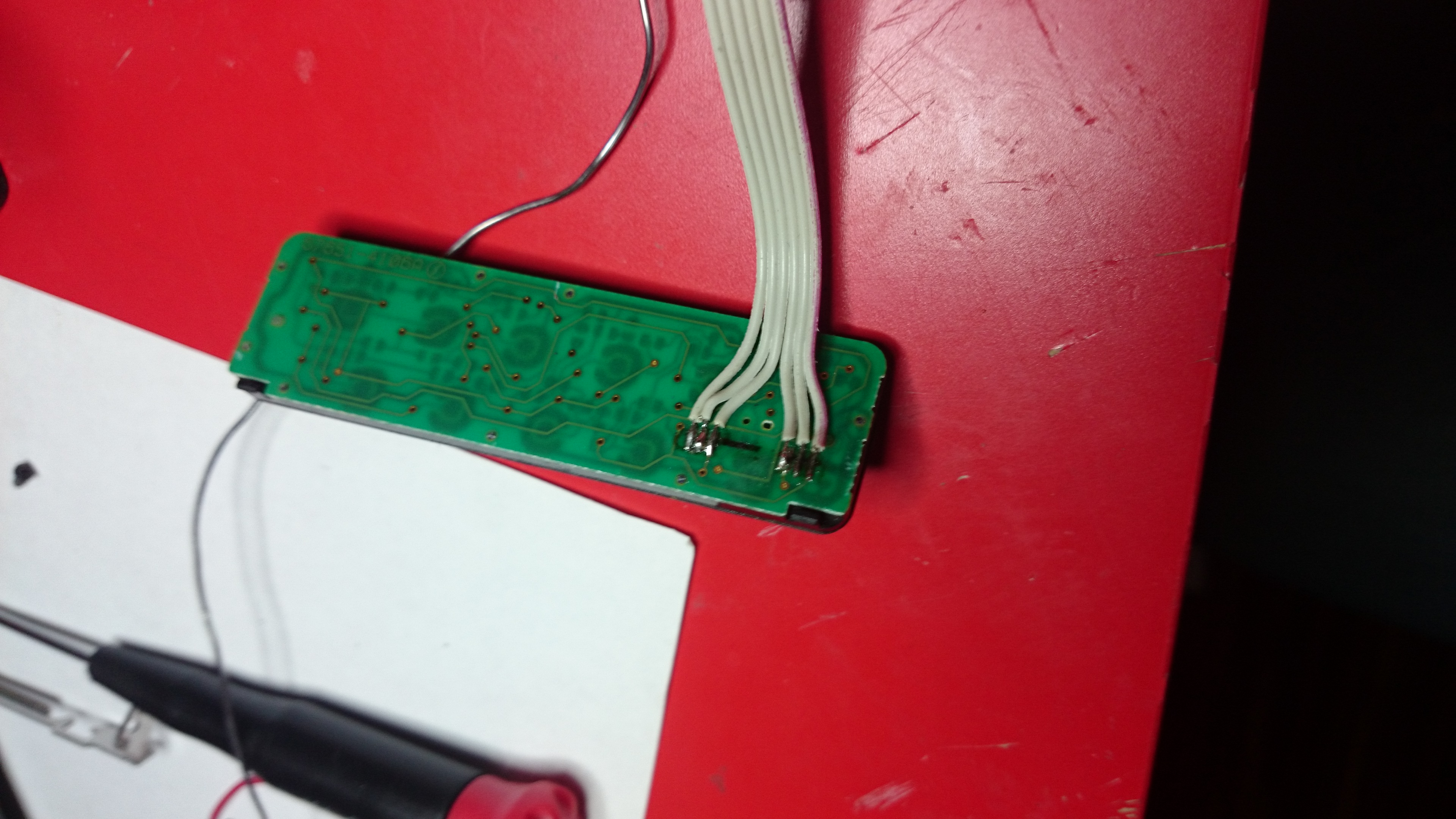
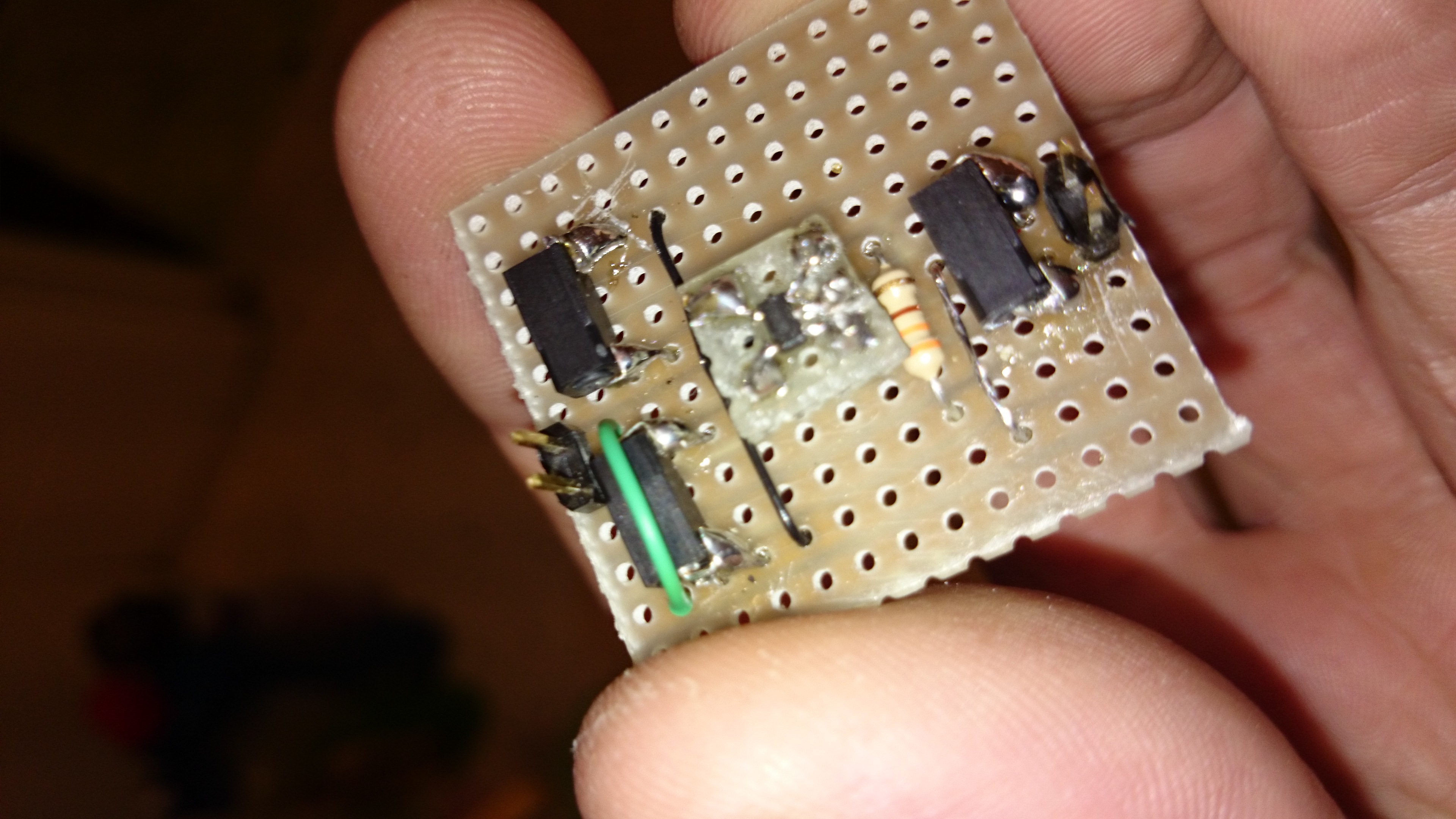
I unscrewed the button panel and cut of 10 plastic pieces that held the controller together and unsoldered the tiny piece of flex-ribbon left on the board. I soldered a flat-cable that i took out of a IDE-cable as a replacement for the broken flex-ribbon. On this side it was quite easy to fit the wiring as there was some space left, once pieces of the plastic was grinded away with a dremel. I resealed the panel with 2 component epoxy-glue and continue to getting ready to attach the other end of these 6 cables.
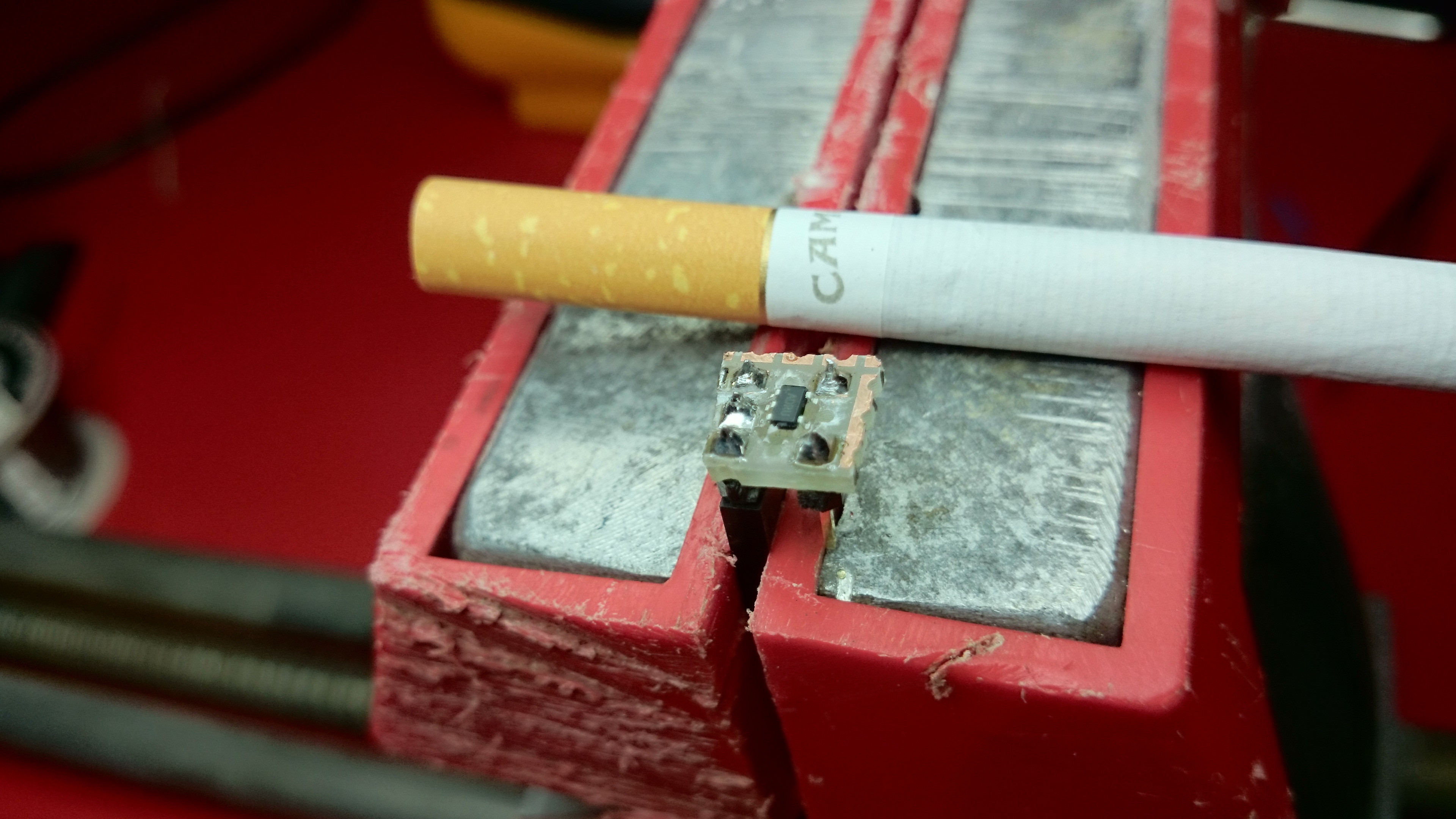
Like i said, soldering something onto a flex-ribbon is not a simple task and having failed before i refused to start doing this on the camera until i mastered it. Luckily i still had the tiny piece of flex-ribbon left from the control. It was only 8mm long but big enough for me to get some practice. As i felt i had control of it, i moved over and started working on the camera for real. Two down, 4 to go:
By placing the soldering’s like a step-stair along the lanes, even these “thick” cables could be connected right on the lanes without short-circuiting any of them. I would lie if i said this was easy and that i did not curse during this whole exhausting 1 hour procedure.
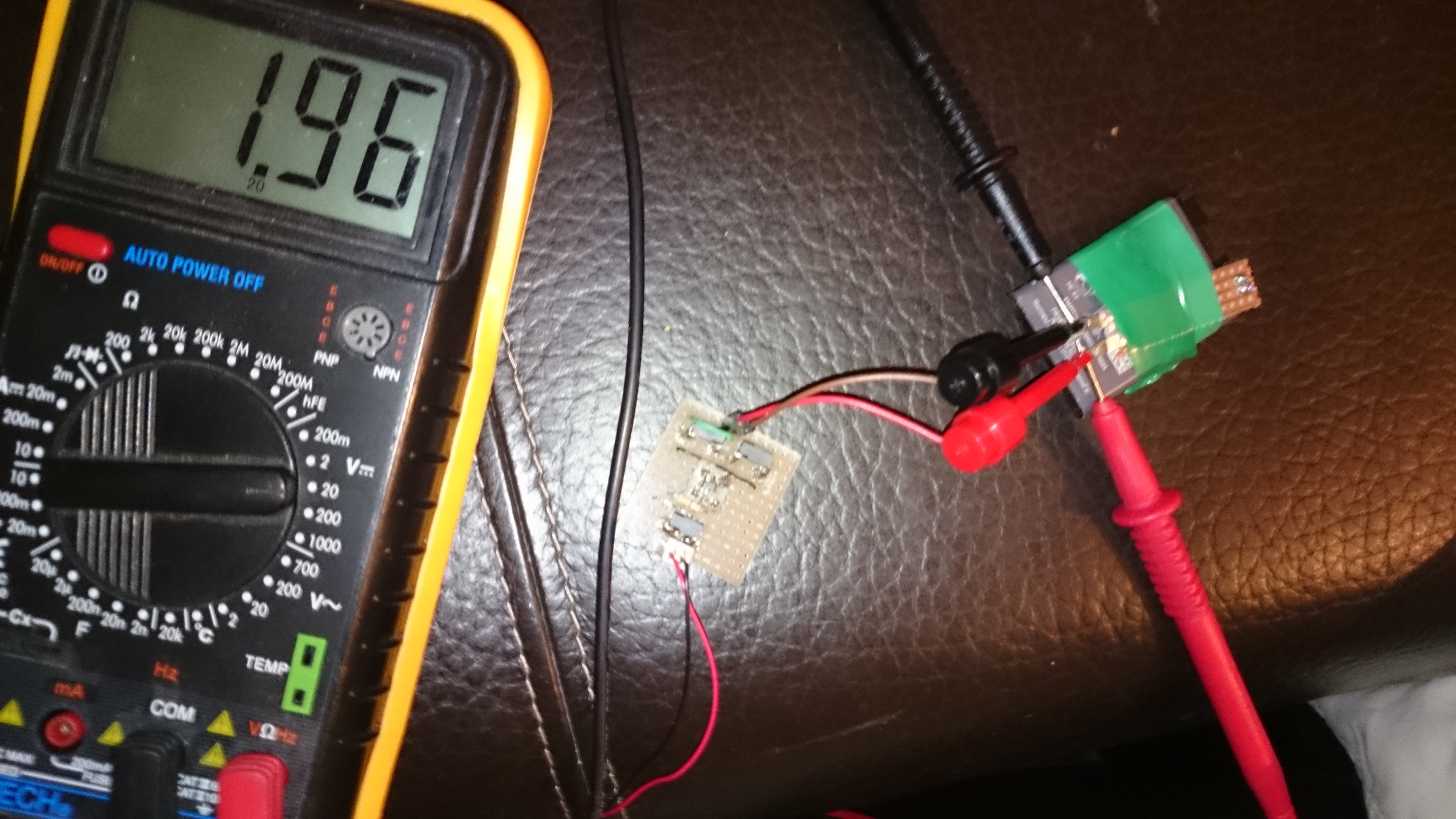
If you are doing something similar and and need to solder on to a flex ribbon my best advise is avoid breathing. Place the replacement wire using a scalpel and once you think you got it where it needs to be, hold your breath and just touch the cable with the solder-iron for a fraction of a second. Make sure you have space around you while working and that cables aren’t being tangled up and potentially destroying your work as you lean out. A good magnifying glass is almost a must. Make sure you don’t support the weight of any parts on these tiny solder-points as it will rip of and potentially destroy more than you just fixed. Additionally take time to verify that every connector is soldered firm and does not cross-connect to other lanes using a multimeter, before connecting the battery/power.
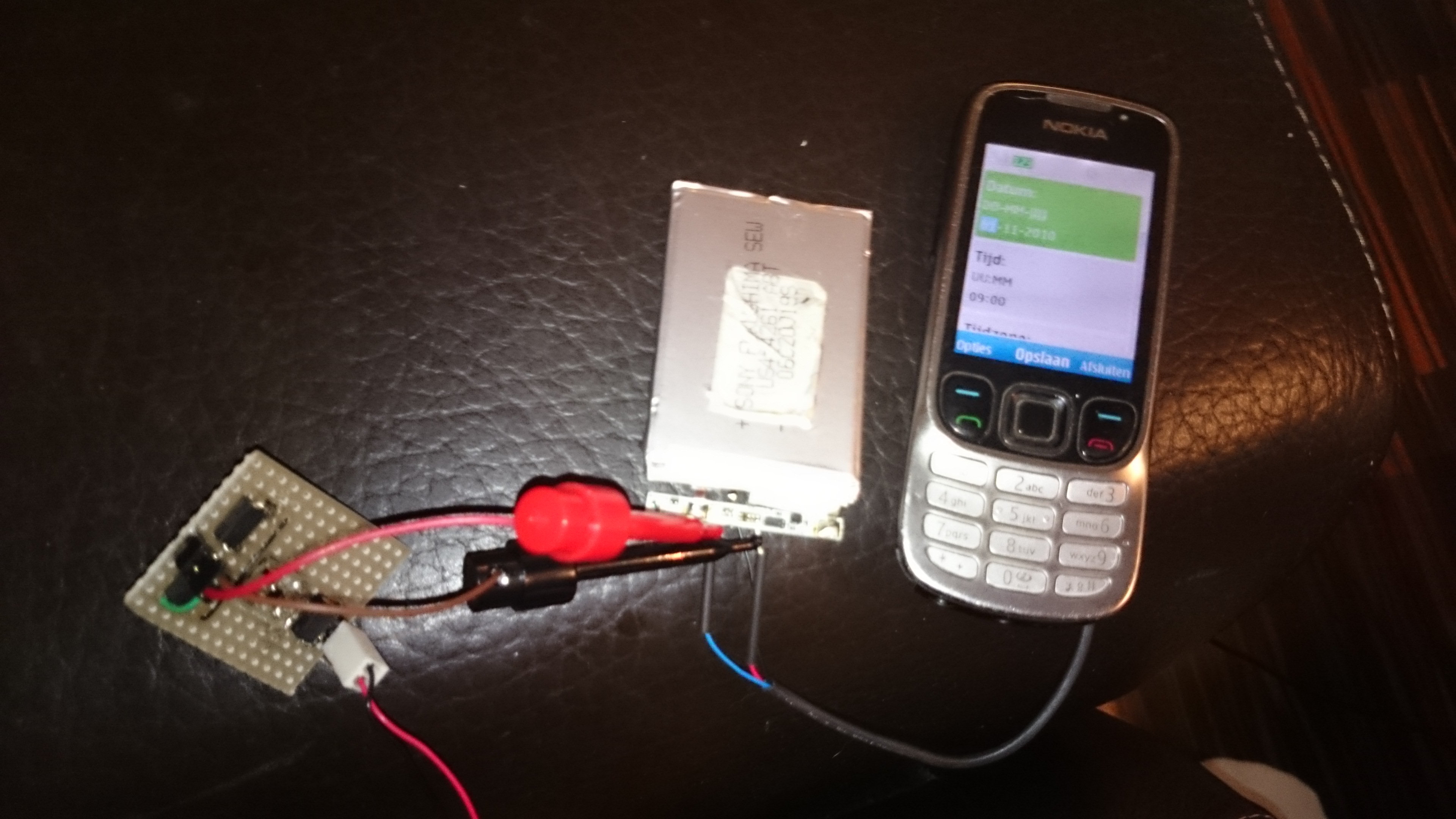
About half an hour into the process the plus and gnd is connected, allowing the LED’s to once more shine:
After all 6 wires are back, i re-mounted the hatch and did a little measurements to verify all was good. All but one line worked but it didn’t take long to find the faulty connection.
Don’t let my cats lack of cooperation undermine anything i have just written, she just hates cameras: