Quite some time has passed since my last real posts, and looking at the car it feels like not much has happened, but re-reading the blog i realized quite a lot did.
No, the massive motor, differential and chain-drive is not in place yet and as you could see in my last blog one of the old gearboxes died. I also mentioned i wanted to keep it rolling during the weekends when my little guy was here, so tearing it all down and start building the drive-chain on the car itself was a no-go for me.
The cat ate the led-lights
And what’s left of it was pulled away by my soon to be 2 years old little rebel :) They will be replaced with more rugged LED strips for actual cars to make sure they get to stay.
I made a few poor attempts to patch the old gearboxes, but ended up removing it all together while awaiting the somewhat beefier replacement 550’s.
These are the RS-550 12VDC doing 23.000 rpm.
The search for wheels end
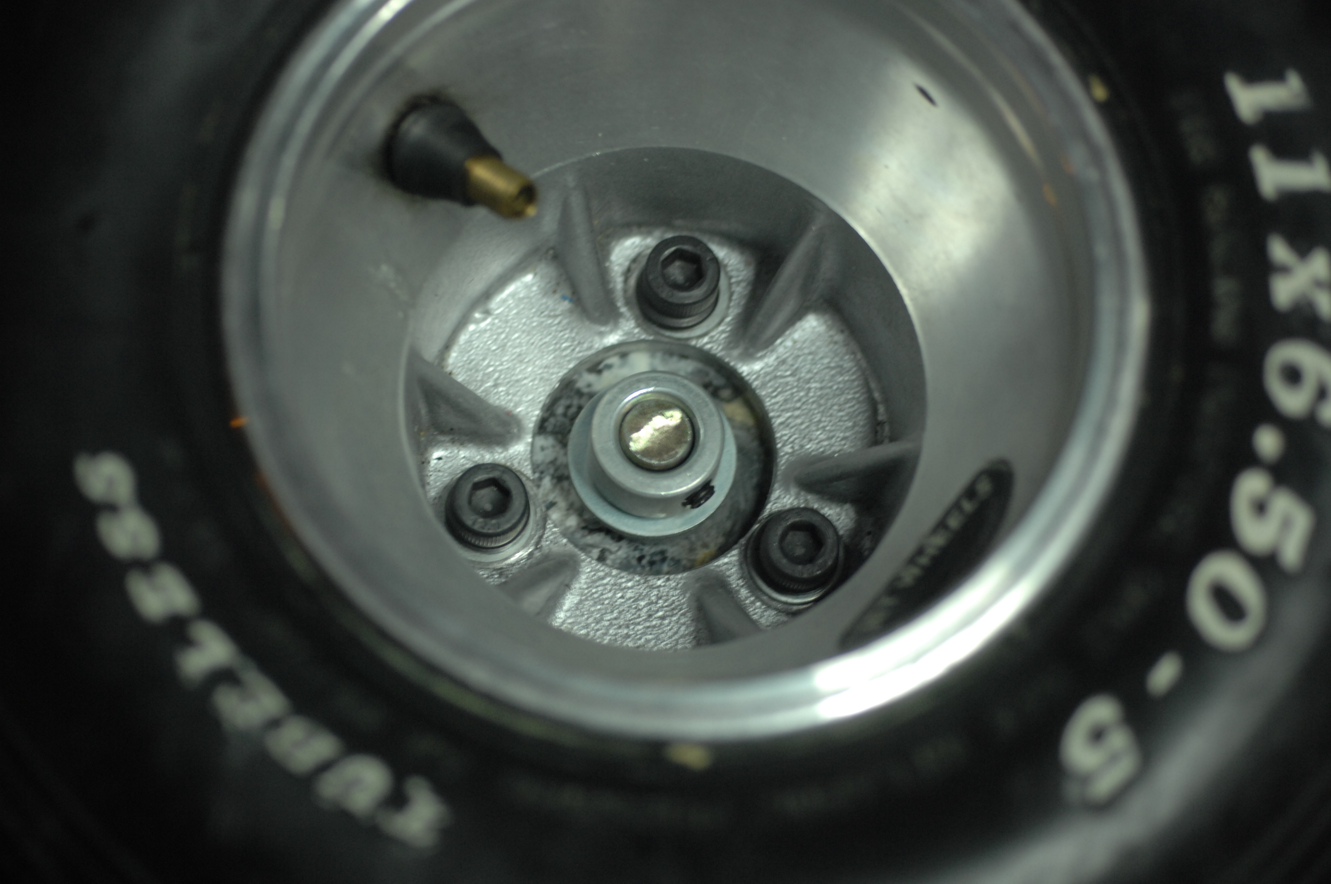
Wheels was an issue, and yes, i went the expensive way with a set of used DeCont gocart tyres.
Front: LeCont 10×4.50-5.
Rear: LeCont 11×6.50-5.
I ended up paying around 160 euros for the set. It looks pretty fancy, i must say and my son loves them.
There is no object so soft but it makes a hub for the wheeled universe. Walt Whitman
I now had wheels but no hubs for the rims to go on and while browsing ebay i didn’t find anything that was reasonably cheap or would just take too long to ship.
Being a responsible adult as i am, i have saved all scrap PLA from failed 3dprints, recycling this makes great sense. I decided to mold them so i measuring the inner diameter of the rim, then ran off to the local food-store and bought two canisters of corn that had just about the same diameter. The cans were emptied, cleaned and put on a the stow in a pan, heated to 210 degrees and the plastic was slowly added to make sure no large bubbles formed.
These chunks were milled flat to size. I drilled and tapped M8 holes and secured the wheel.
Art consists of limitation. The most beautiful part of every picture is the frame. Gilbert K Chesterton
I also started building the frame that once finished will replace much of the under-carriage of the current car. The game-plan is simple. Build a rolling frame with suspension, brakes, gears, differential, steering and motor and once ready transplant that frame to the car. Until now i started created 3 revisions of the back-end but stopped half way and reflected over decisions, scrapped it and started over again. This is most likely nothing what it will look like when “done”.
I have used aluminium as much as possible to keep the weight down. I got my hands on a 1300x60x40mm u-profile that shapes the base of the frame. The barrings housing holding the differential had to be milled down slightly, and 10x15mm strips add supports.
Initially flaky lower control arms moved me from cheap hollow tube, to solid square stock, to end up with 10mm thick aluminum blocks at the end.
I have been able to do most of the milling on my tiny Proxxon MF70 Micro-mill, but i REALLY need a bigger machine that eats more material, preferably CNC but for now this will have to do.
Rear differential, bearings, chain, chain-tentioner, electric motor and the lower control arm mounted. Battery box will be mounted on the opposite side to the motor to balance out the weight.
All of this will be covered under the driver seat to avoid anyone losing a tiny finger. I am considering to add linear actuators to the suspension to be able to raise and lower it as i think it would make it look sleeker. Not sure yet, leave your comments.
The child supplies the power but the parents have to do the steering. Benjamin Spock
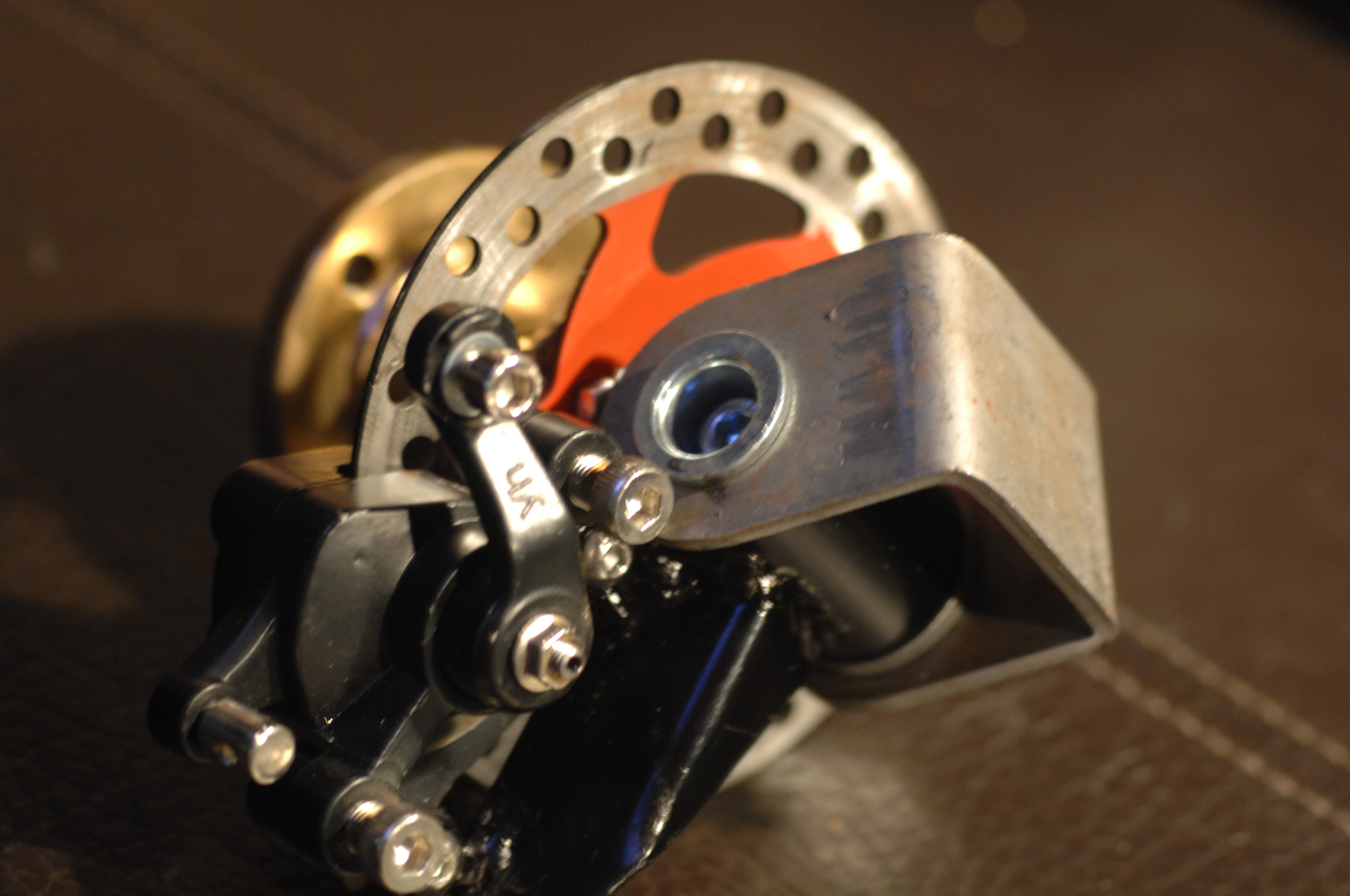
I bought a gokart front steering kit, including wheel-hubs. I welded a few nuts and bolts to them allowing the pocket-bike disc-brakes and calipers to be mounted, then gave them a splash of paint.
Life is made of ever so many partings welded together. Charles Dickens
I ended up buying a dirt-cheap 200 amp MMA/TIG. I burned a few boxes of rods and i am starting to get the feel of it. And yes, I even welded aluminium, but like everyone said, it’s hard to do with stick (however not impossible).
So far this project is moving a lot slower than i am wished for but it’s busy days and i have spent a fair amount of time picking up milling, using lathe and welding. With this mix of new trades i am reconsidering a lot of decisions made prior to posting here, so you have not seen half of it.
Anyway, just wanted to let you know i was making some progress.
As i promised a lot of the future posts will be about hacking toys.
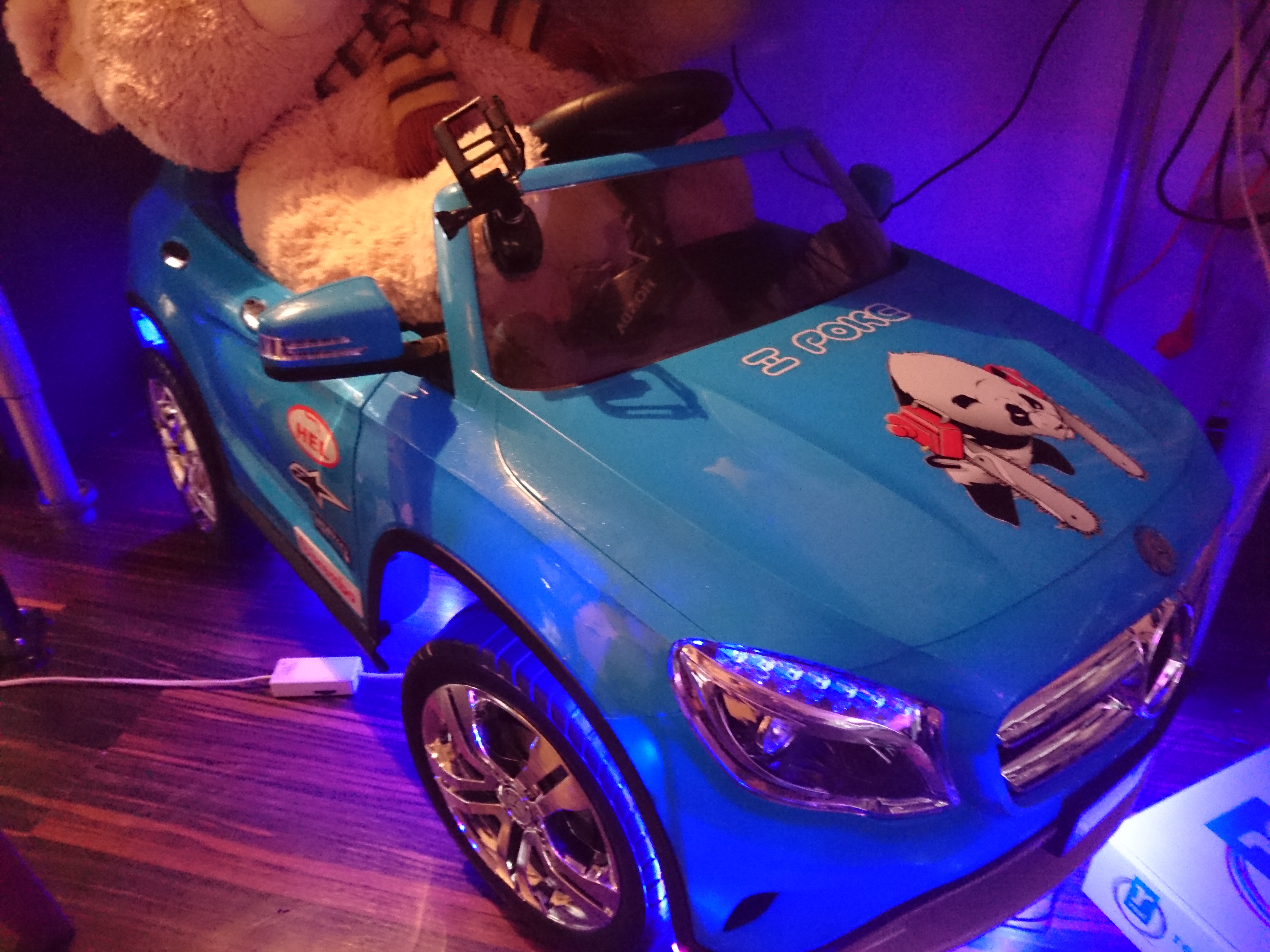
In November i bought this Mercedes GLA Class Ride-on kids car for my 1 year old son, a car he loves so much but i have a feeling he will never love less as this build progresses.
Its about 120 cm long, 60 cm wide, 50 cm high and weighs in at around 25 kilos.
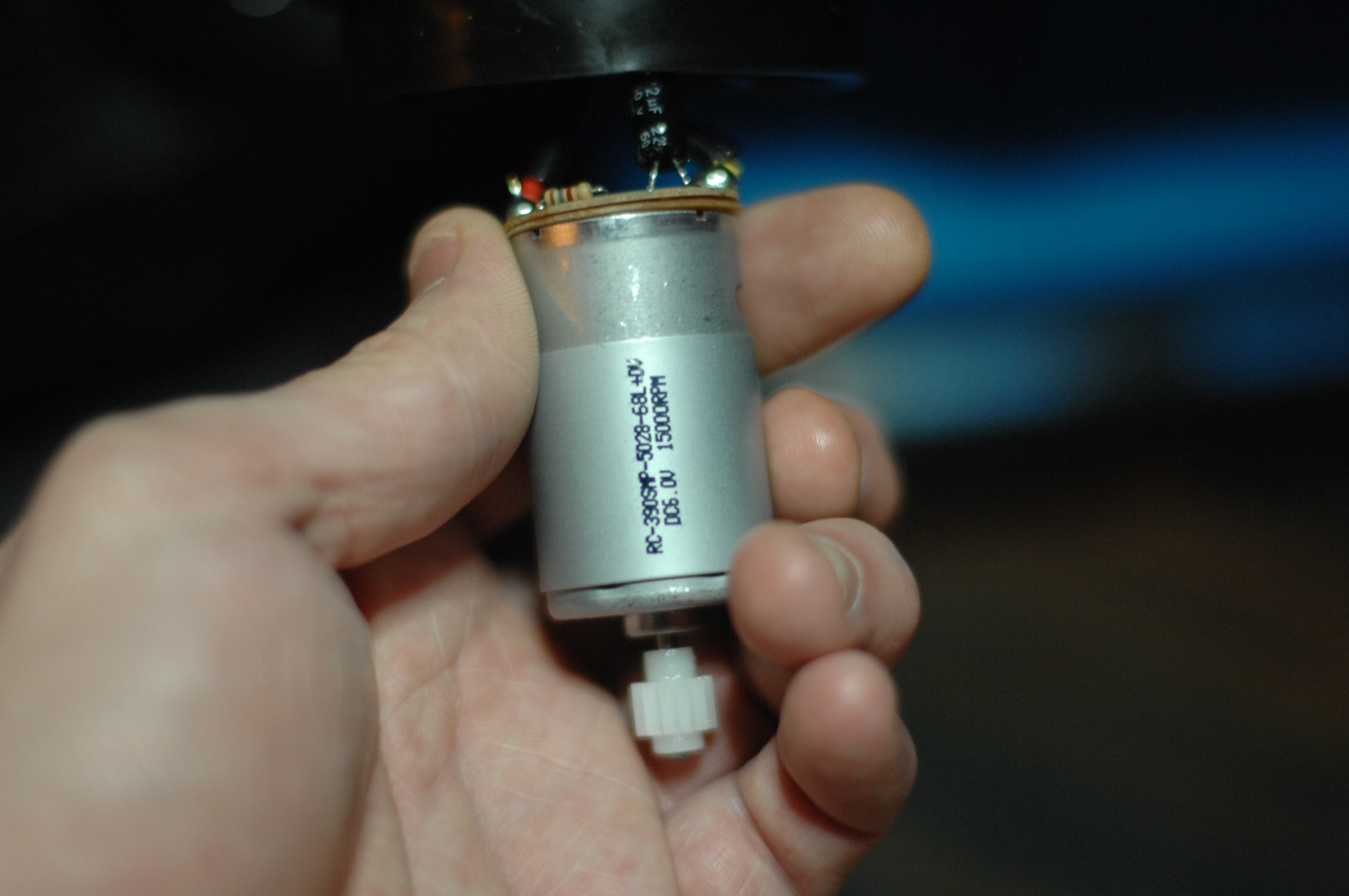
It costed about 250 euros and can be driven from the car or controlled by remote. The car has 3 emulated gears, each allowing the motors to higher rpm’s the higher the gear. I say motors, because this model have 2 separate 6 v engines (of type 380/390) which are serial-connected to the 12 volt relay in the receiver. The top speed is 5 km/h. The engines the car came with:
RC-390SMP-5028-68L DC6.V 15000RPM
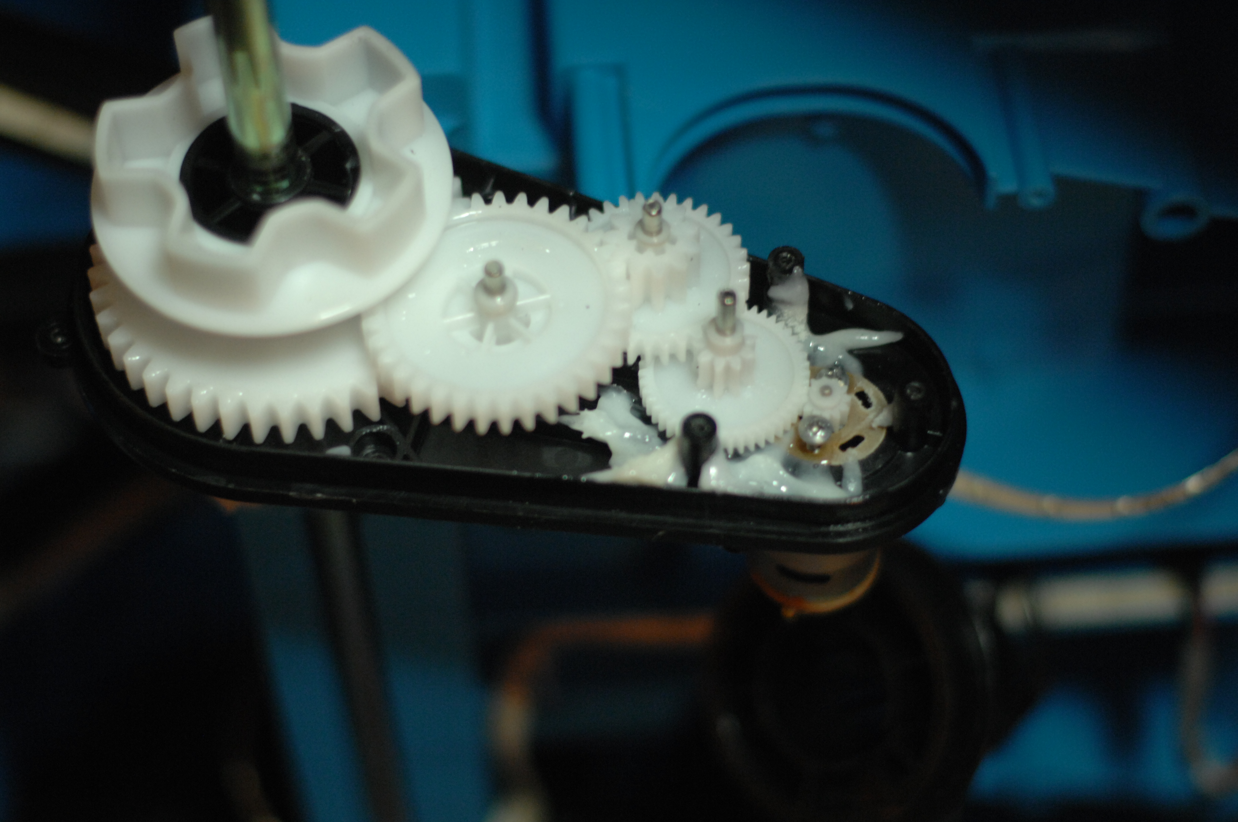
Gearboxes use all-plastic cogs, which is all good in it’s original state, but this might have to change to support what i want to do:
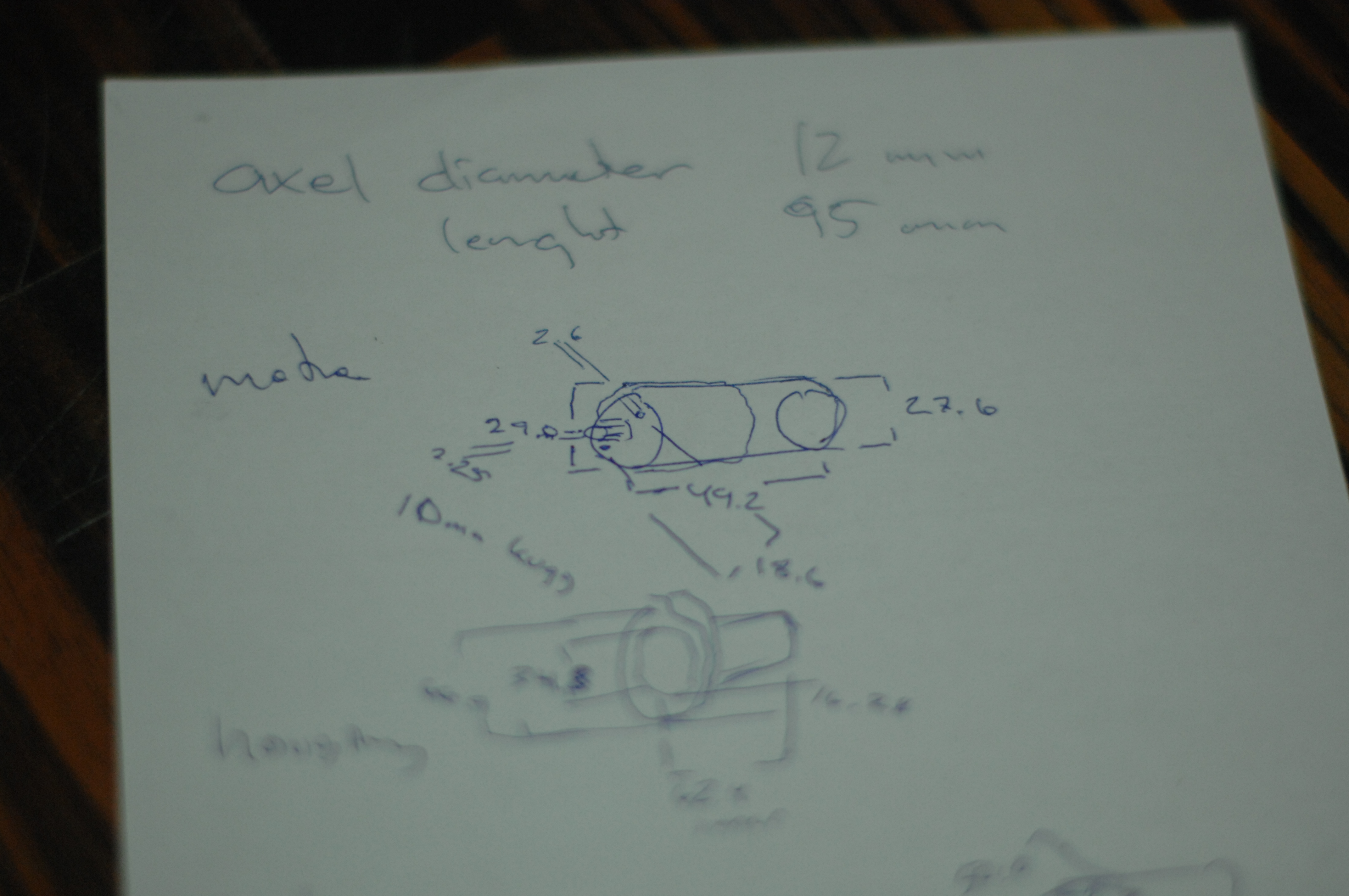
Knowing nothing about the motors (initially that was) i took some measurements and started to google:
The controller is kind of a all-or-nothing switches, which makes you zig-zag to the left and the right to keep a straight line while driving it using RC along narrow curbs. They added a acceleration lag in the power-on to soften the jerkiness a bit, but unfortunately they didn’t not managed to do the same when dropping the gas, so stopping is pretty abrupt.
Additionally it has a 6 songs “stereo” , with a 3.5 mm stereo-plug. The songs are well composed mixture between kids music and electronic dance but 6 songs gets boring fast so this is on the change list. When pushing the start-button you hear a roar of the motor, and pushing the horn makes a “mepp-mepp-mep-mep” tone.
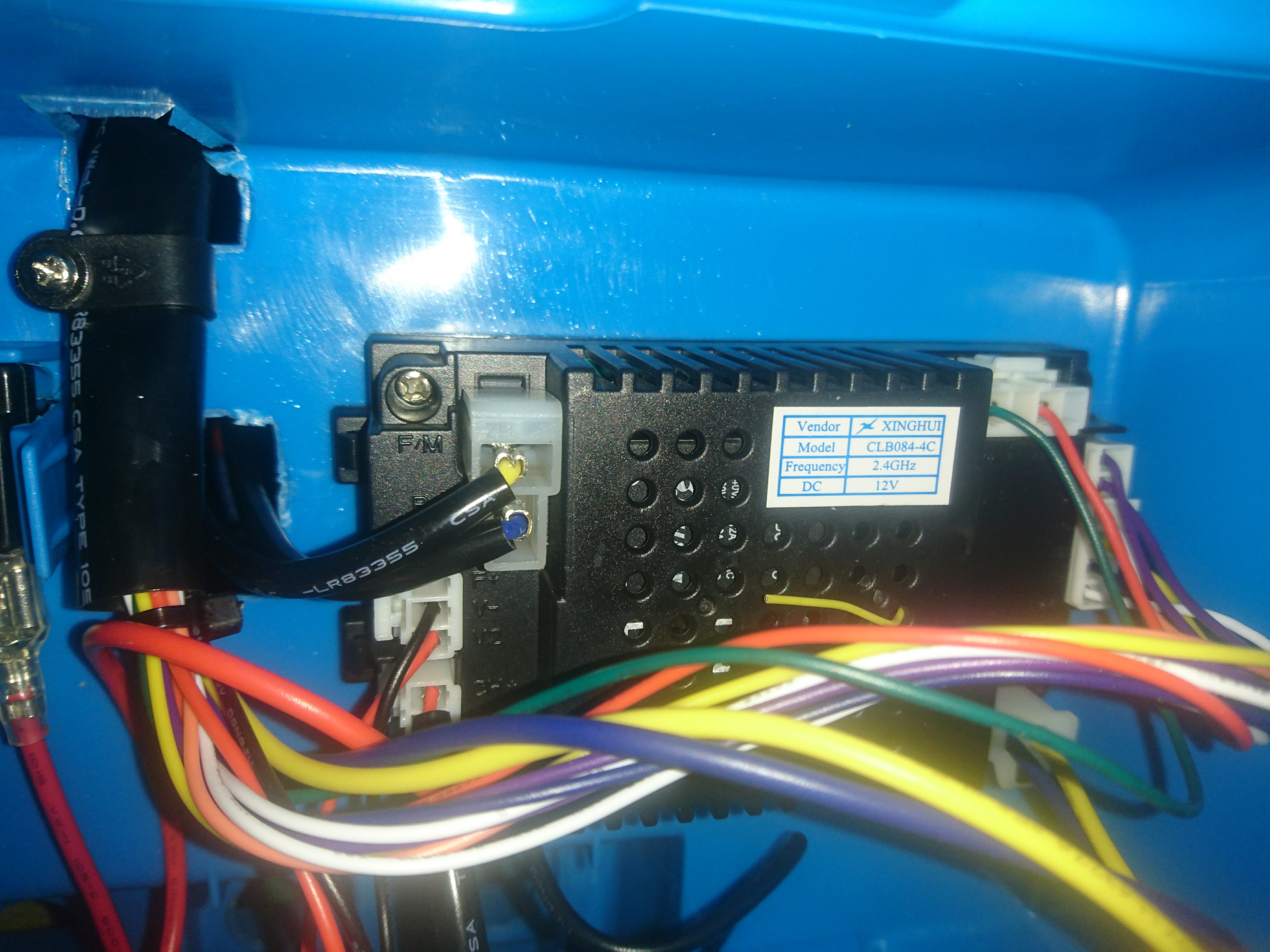
Xinghui CLB084-4c 2.4 ghz receiver, charger, motor controllers and stereo.
The receiver can be found on Aliexpress, but a pdf with all pinouts have turned out to be harder to get my hands on. That sucks, as I see pins that are unused meaning it might have more features I don’t know yet. Will reverse engineer it later. All in all it’s a funny toy for it’s price but a lot of improvements can be done.
So what am i planning to do with it?
Well, i have a lot ideas but some cost a bit of money and some are hard to source parts for and some will simply be unsafe.
It should be a little faster, with softer acceleration and braking.
Replace the radio-controller/receiver, with something a bit more professional, less jerky and with lots of spare channels to control all the electronics.
Proper rubber tires giving traction and look better. A few options out there, but I haven’t found exactly what I want.
A proper stereo with some umpff!
Individual brake disks on the front wheels to be able to do burnouts.
Melody horn.
Proper seat-belt 3 or 4 point, new seat even?
Let’s get started.
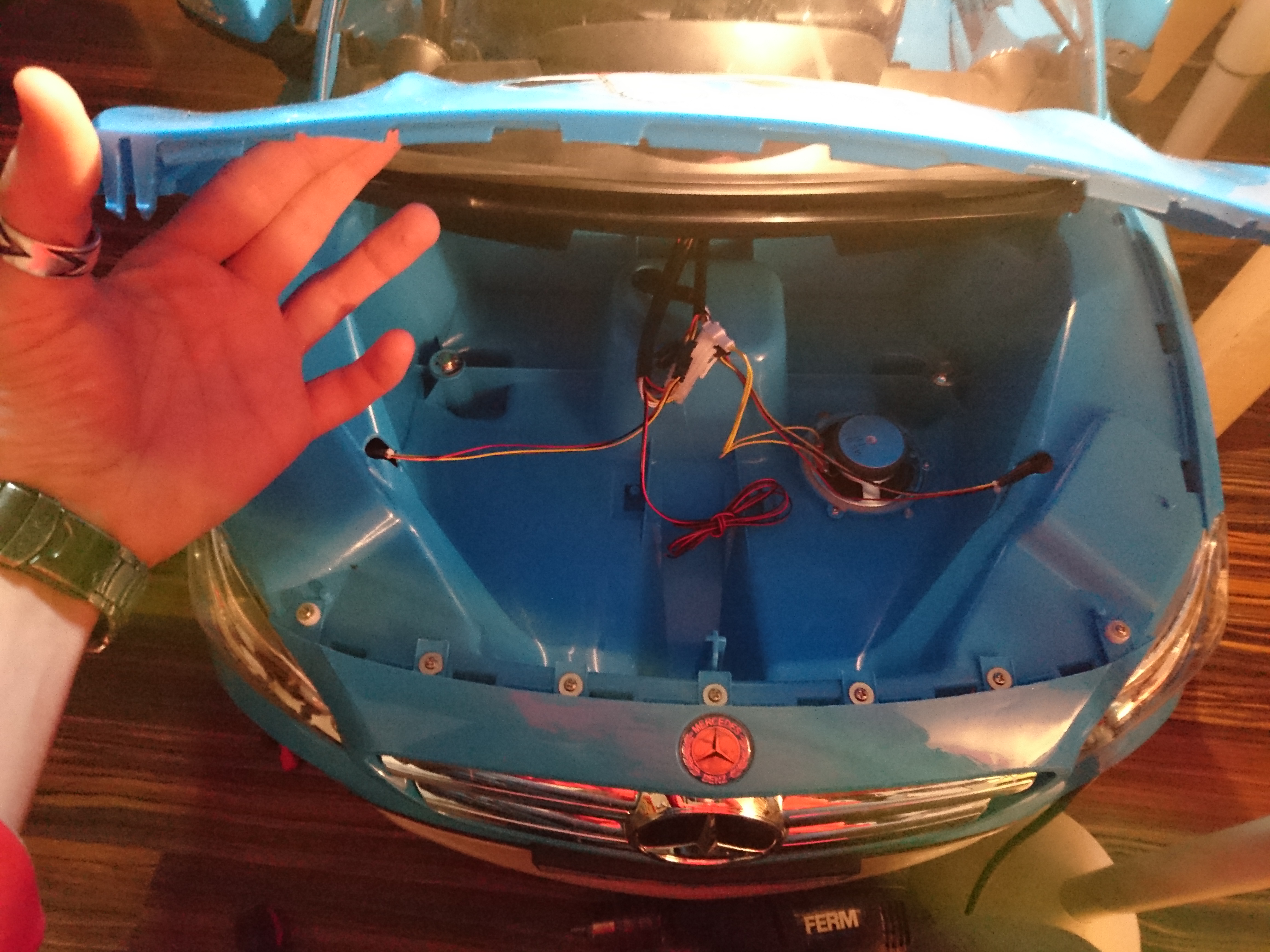
The first thing that struck me when i started screwing it apart was how much space there is left in it. The the hood is screwed down, but once unscrewed yet another gigantic rather empty space is reveled. Same goes for the trunk. Ohhh the potential :)
So where does one start?
Let’s go with the low-hanging fruit. Nothing says car-tuning like RGB LED-stips, and it’s something my son would notice directly so that’s what i went for. End result looks (and sounds) something like this (hosted video on youtube, as i slashdotted my hosting company yesterday thanks to HackerNews):
A second fast win would be stickering it with some AlpineStars, Brembo, Hel performance and GoPro stickers. I had a left-over “i poke bear”-sticker from the pimping of my zx636 ninja, so that went on the hood too.
Speaking of the hood, i mentioned i opened it up however seeing the hood open made me think it should not be screwed down ever again. I made 2 temporary hinges with a glue-gun and two screws, and cut off the majority of all the flanks that held the hood into place making the area easily accessible for future upgrades.
The open hood reveals a lot of free space and a mono speaker.
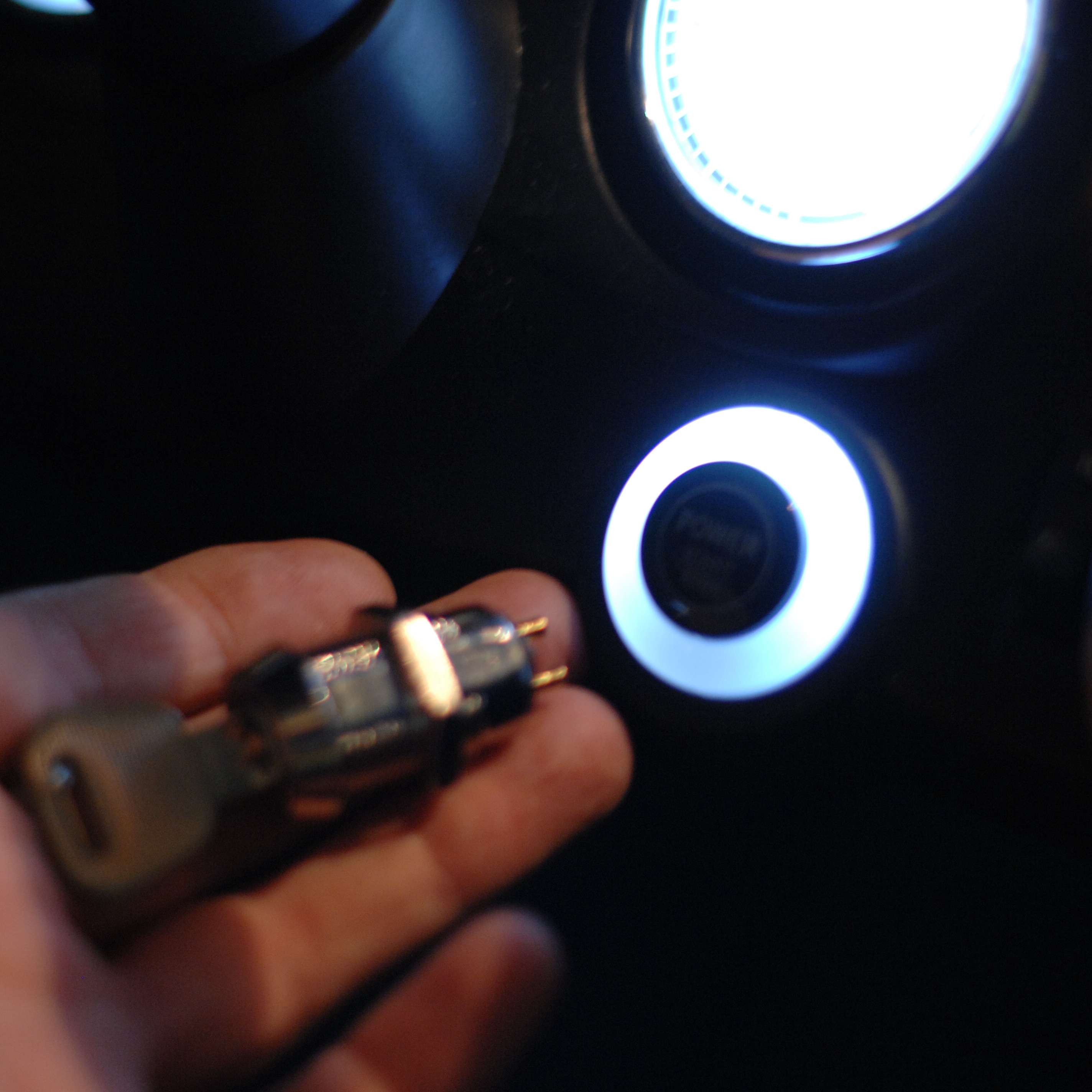
Ignition-switch:
My little guy is totally fascinated by keys, so needless to say he needs an ignition-key. I found this little switch in one of my favorite stores around the corner, Rotor-radio Amsterdam.
To get it into the car, i had to unscrew large parts of the car.
Then solder it into the harness where the old switch was connected.
Tada!
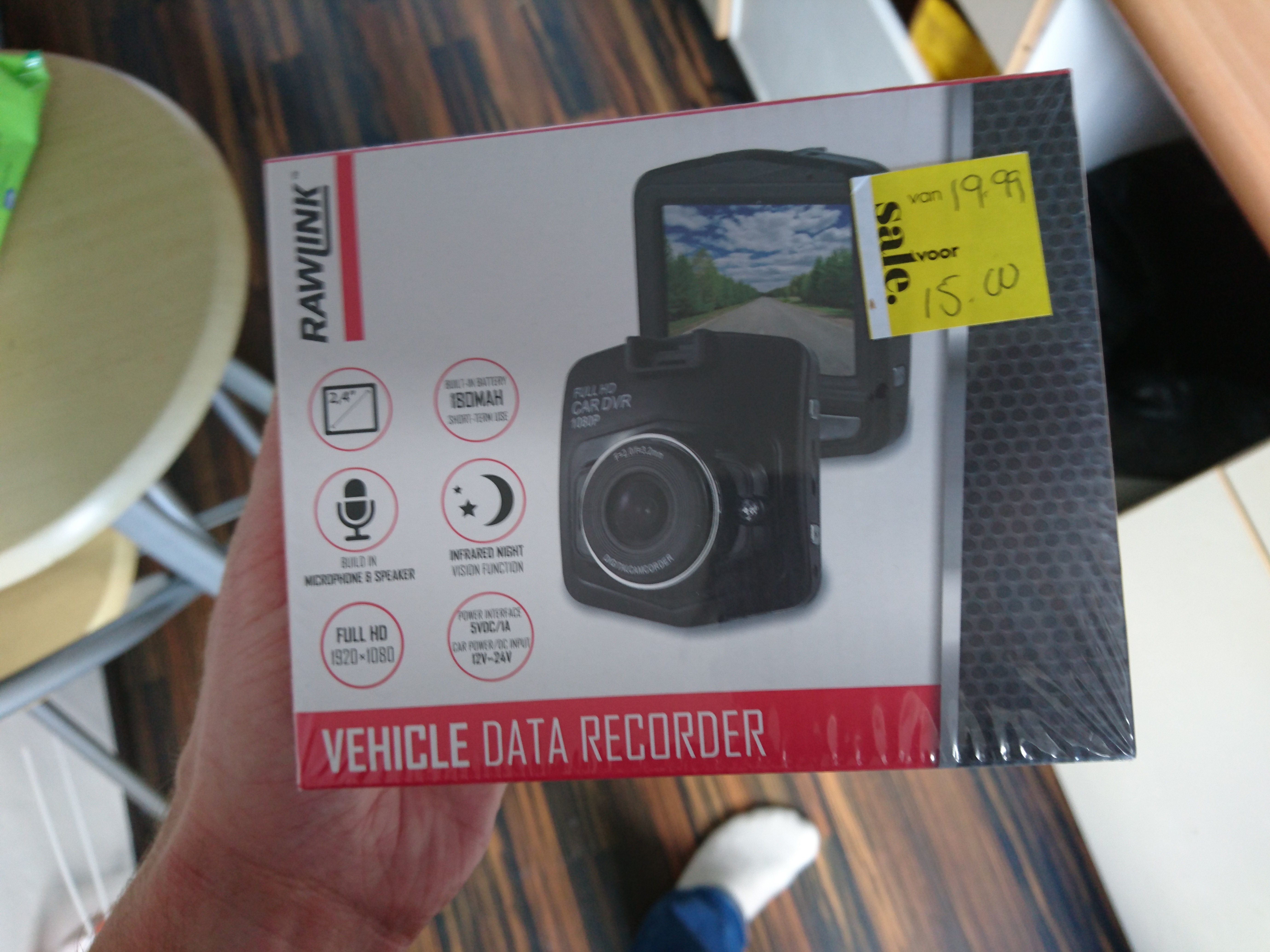
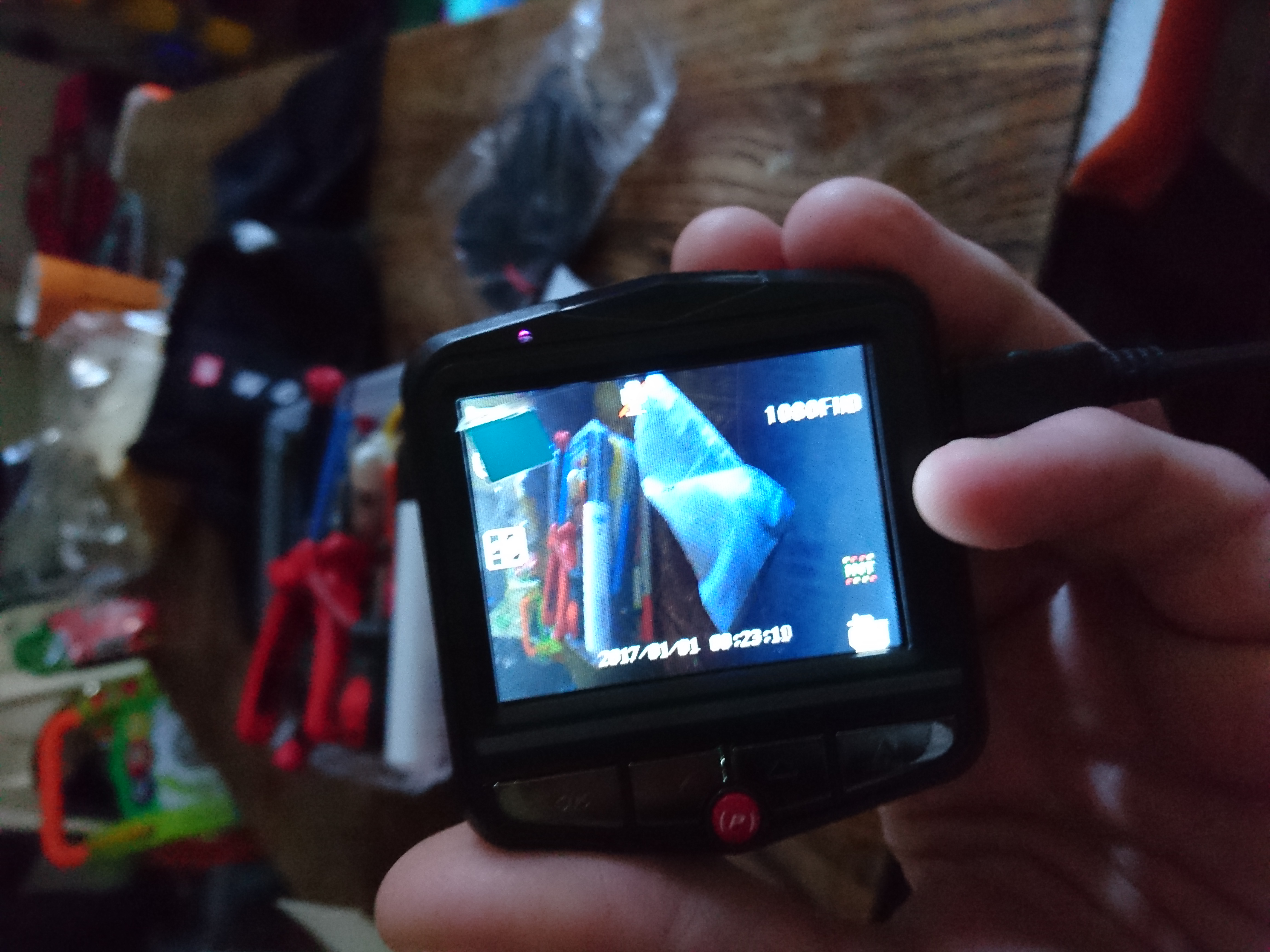
Reversing camera.
I found this super-cheap dashcam, and decided it would make a great rear reverse camera:
Quality of the picture is great and it also has night-vision :)
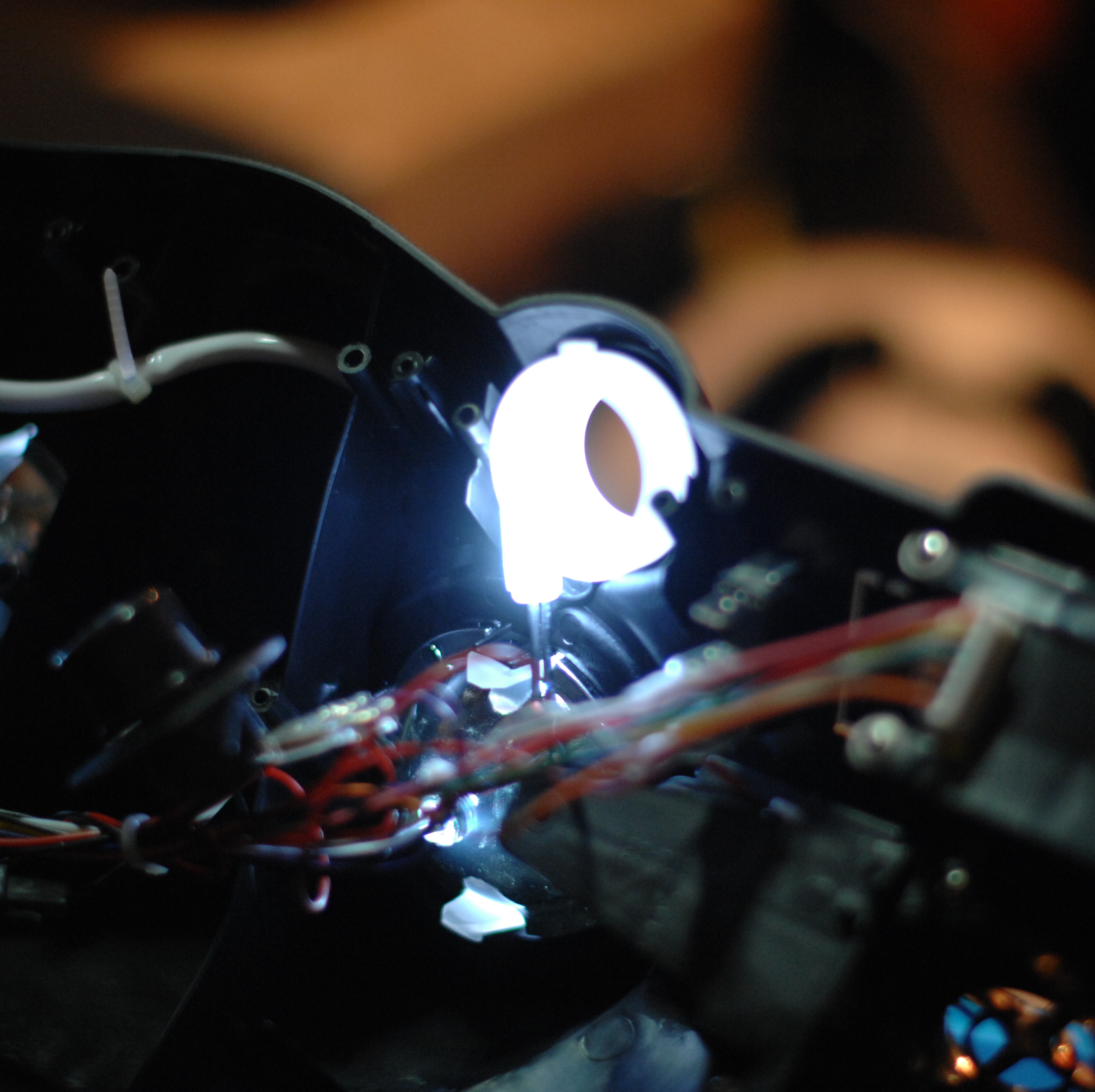
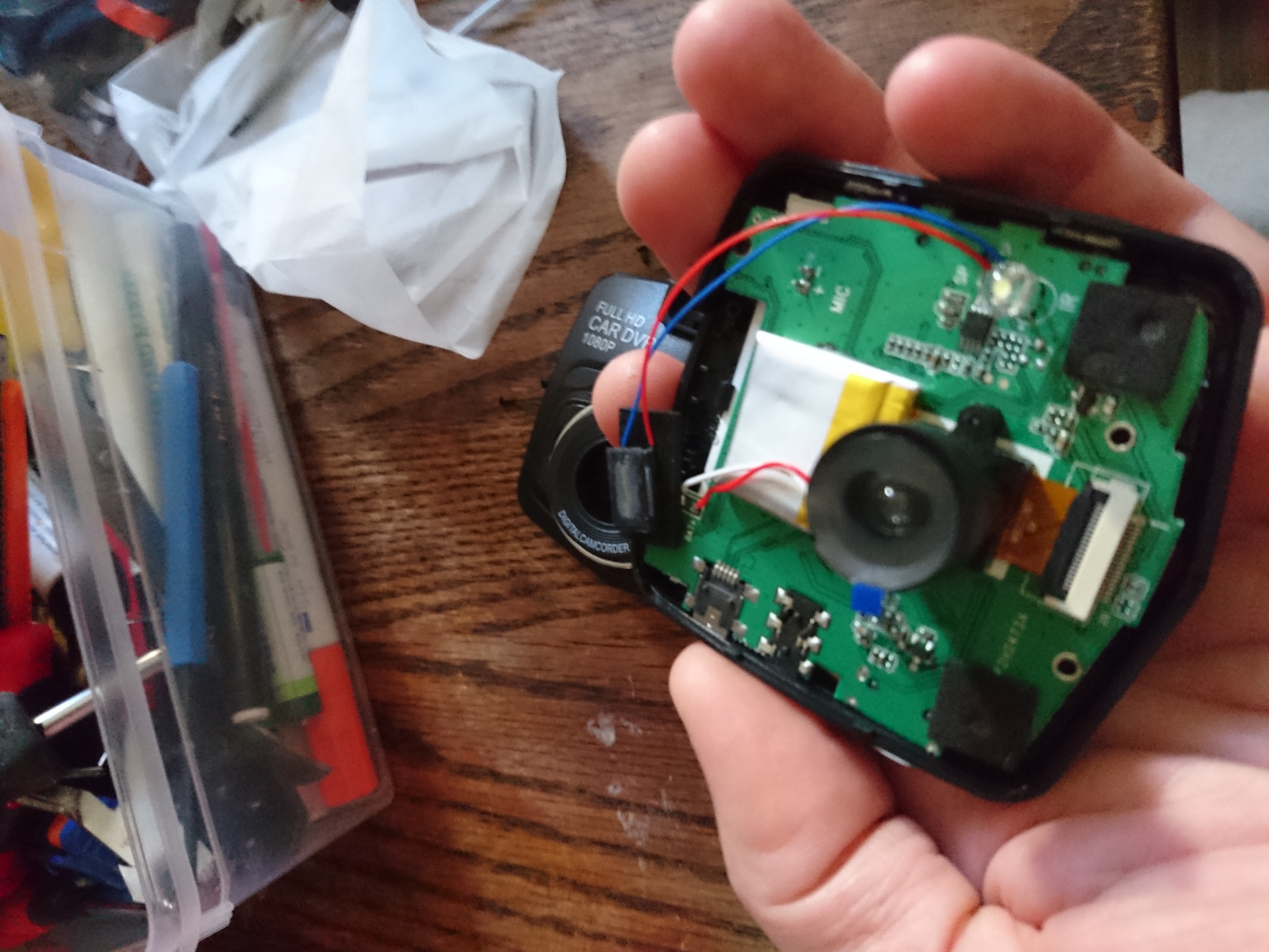
Opening it up, shows i will have to solder 17 wires to separate the camera from the circuit-board:
Not impossible but since i intend to install a proper stereo in the dash too, it makes sense putting this on ice until that is done and I know how much space is left.
I got the power!
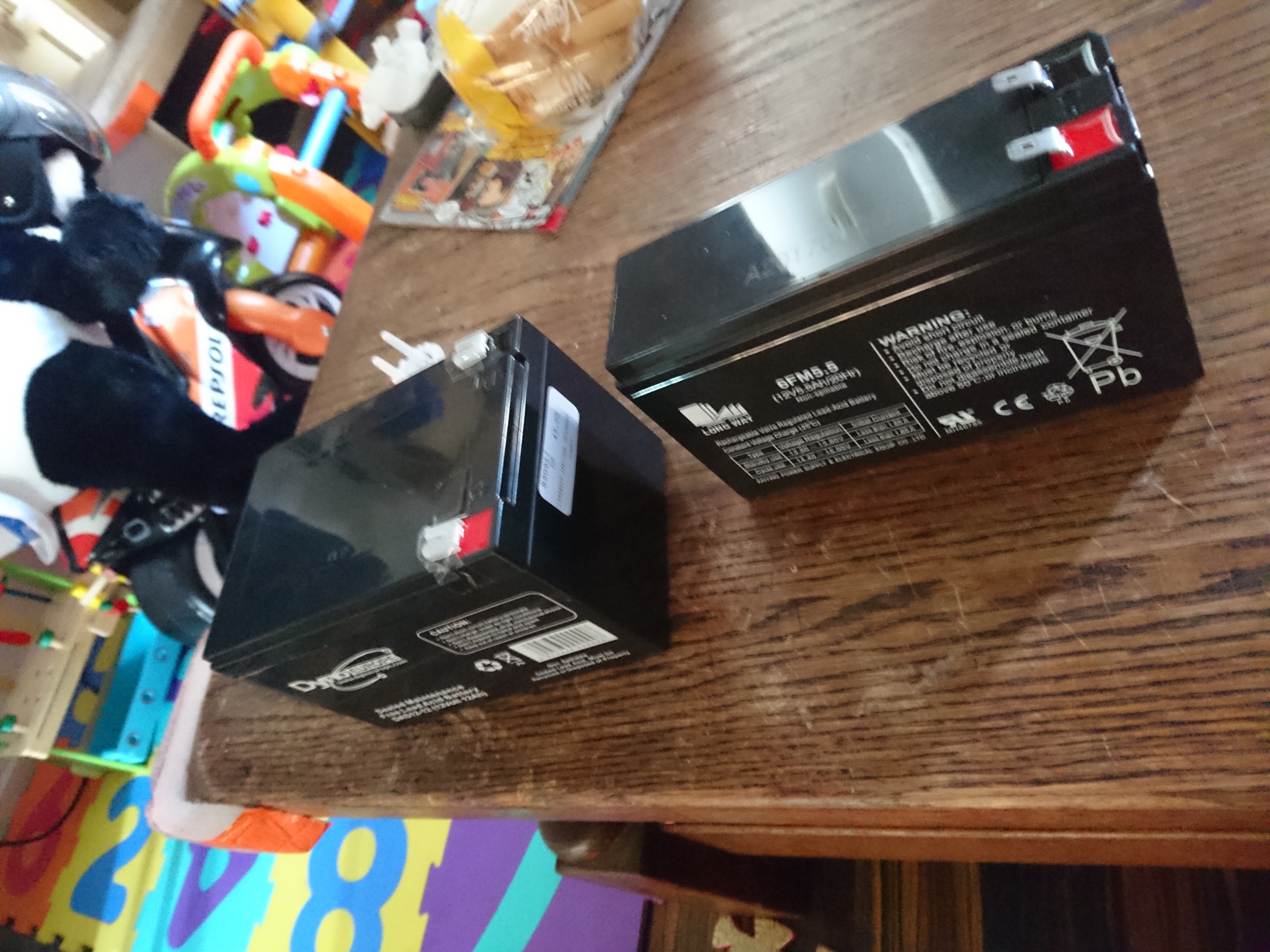
So far i have not run into the limitations of the battery, but my son is quite young and we only do small rounds with it. However i plan to stick a lot of electronics in this beast so a larger battery makes sense. The car actually had room for the larger battery where the old one was mounted
I replaced the 5.5Ah 12 volt lead-acid with it’s 12 Ah big brother.
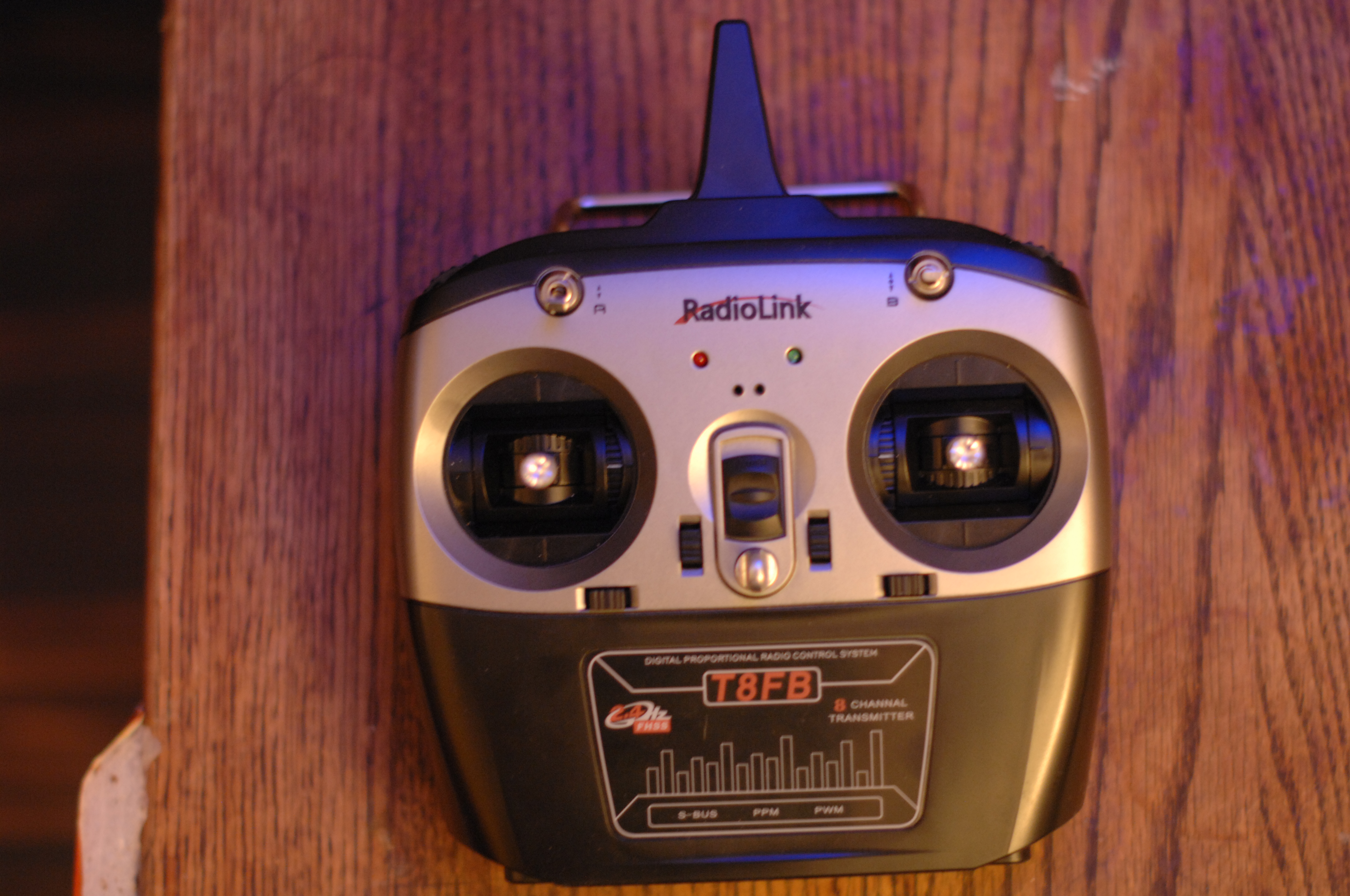
With brakes, LEDS and what-not, i decided to buy a 8-channel radio. I can only hope this scales to the ideas i have but we will see:
RadioLink T8FB
Getting the radio ready!
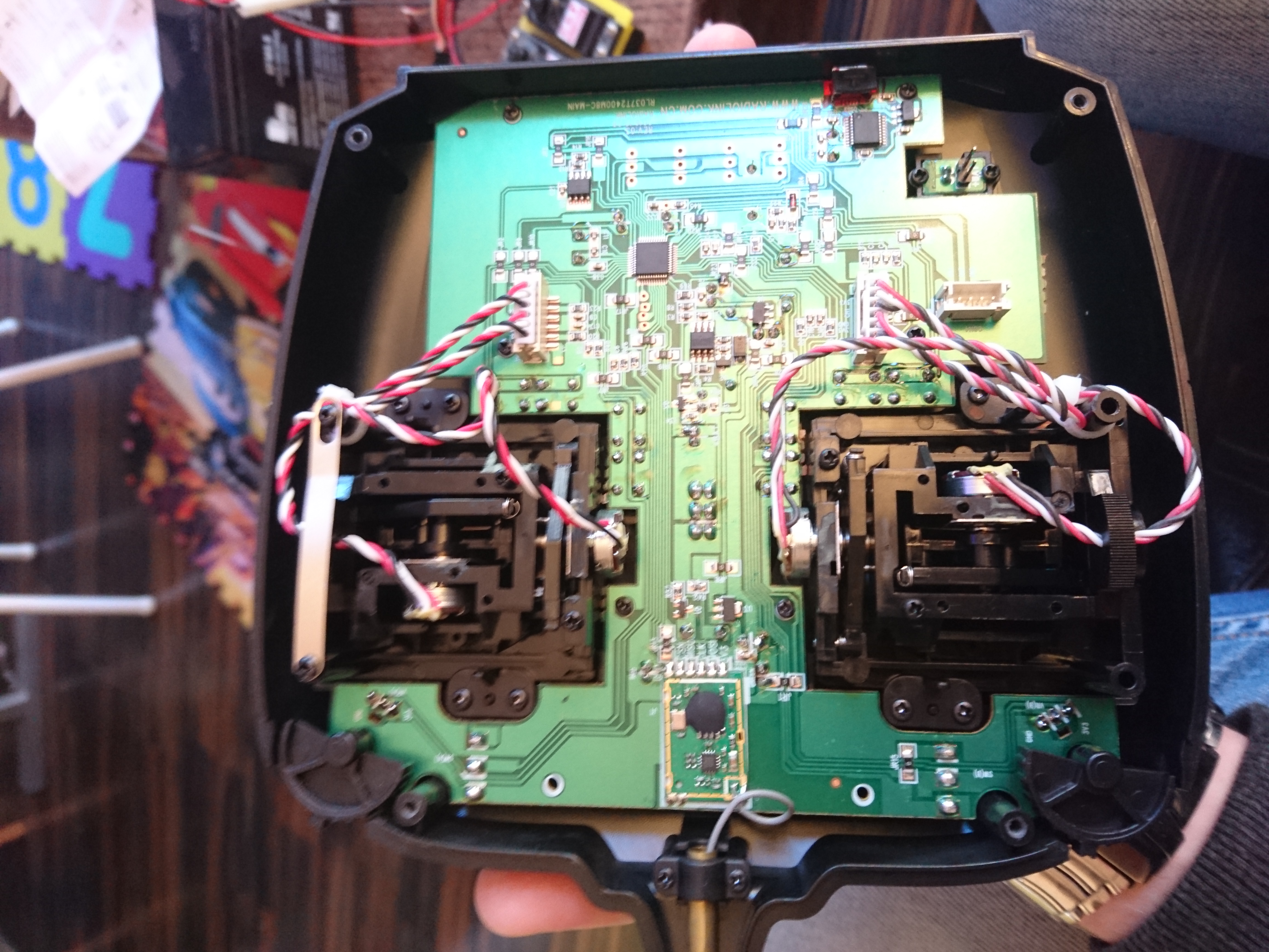
I have never built a radio-controlled car from scratch so selecting ESC, servos, motors, batteries was all done ad-hoc, while googling around. This radio is intended for plane/helicopters, so i started by reconfigured the control to spring back the left hand stick when released:
RadioLink T8FB opened up.
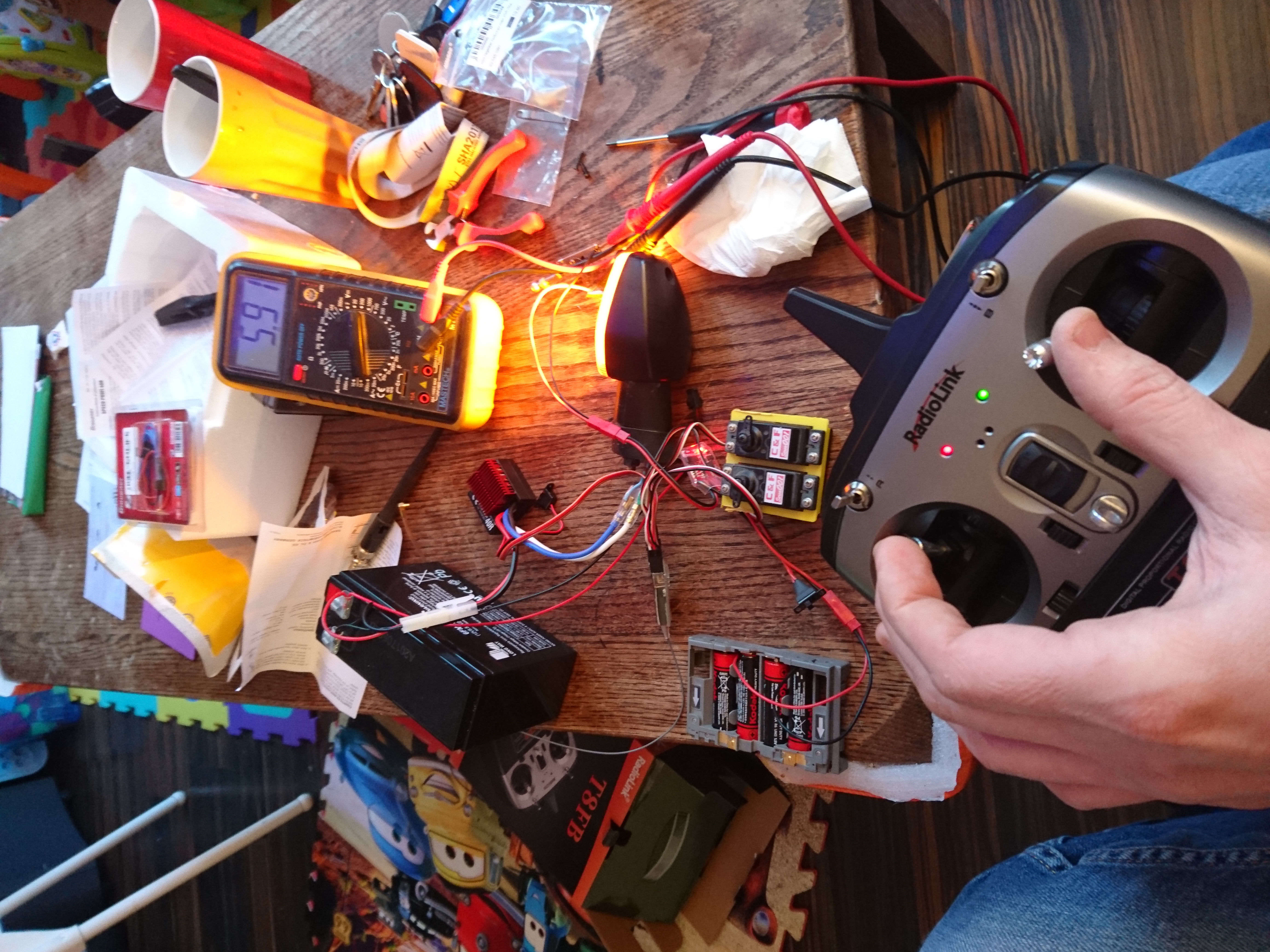
For the drive-line i choose a 40Amp 12 volt ESC from Graphner. Two old servos from a small electric plane simulated the servos for the brake-disks and a smaller ESC to control steering.
The old fireblade blinker is connected to the 40Amp ESC to verify that all works. Having it all on the table like this allowed me to calibrate servo’s and ESC’s in a simple way.
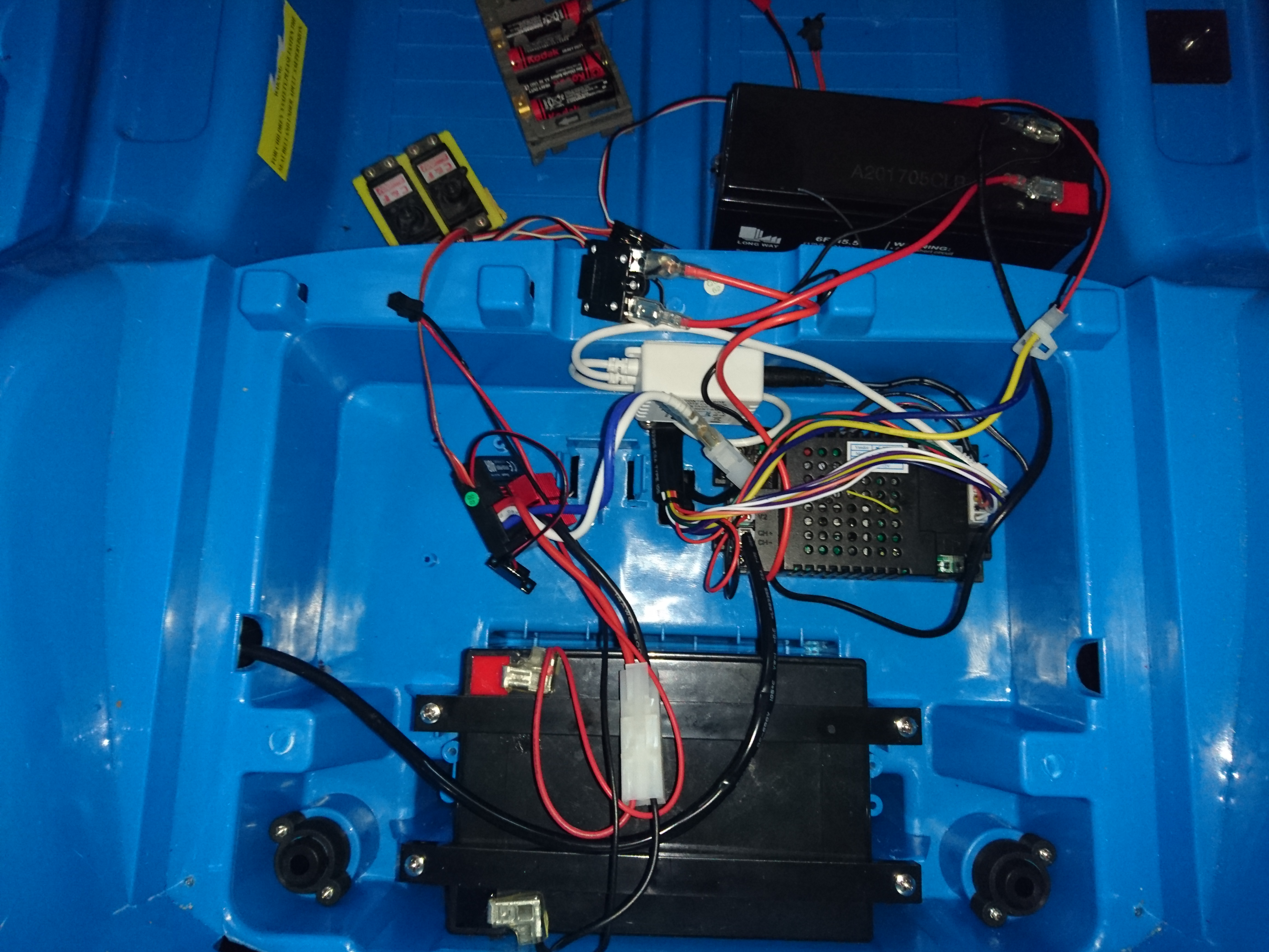
Once that seemed to be working i hooked it up to the car. As my son would be very sad if his stereo did not work, i left as much of the old electronics hooked up in the birdsnest you can see below:
Nested the new rc-parts into the original wiring, and it works.
This means that i now can control the car over the 8 channel radio, while still providing power to the old electronics that allow the fake engine sounds and “stereo” to work.
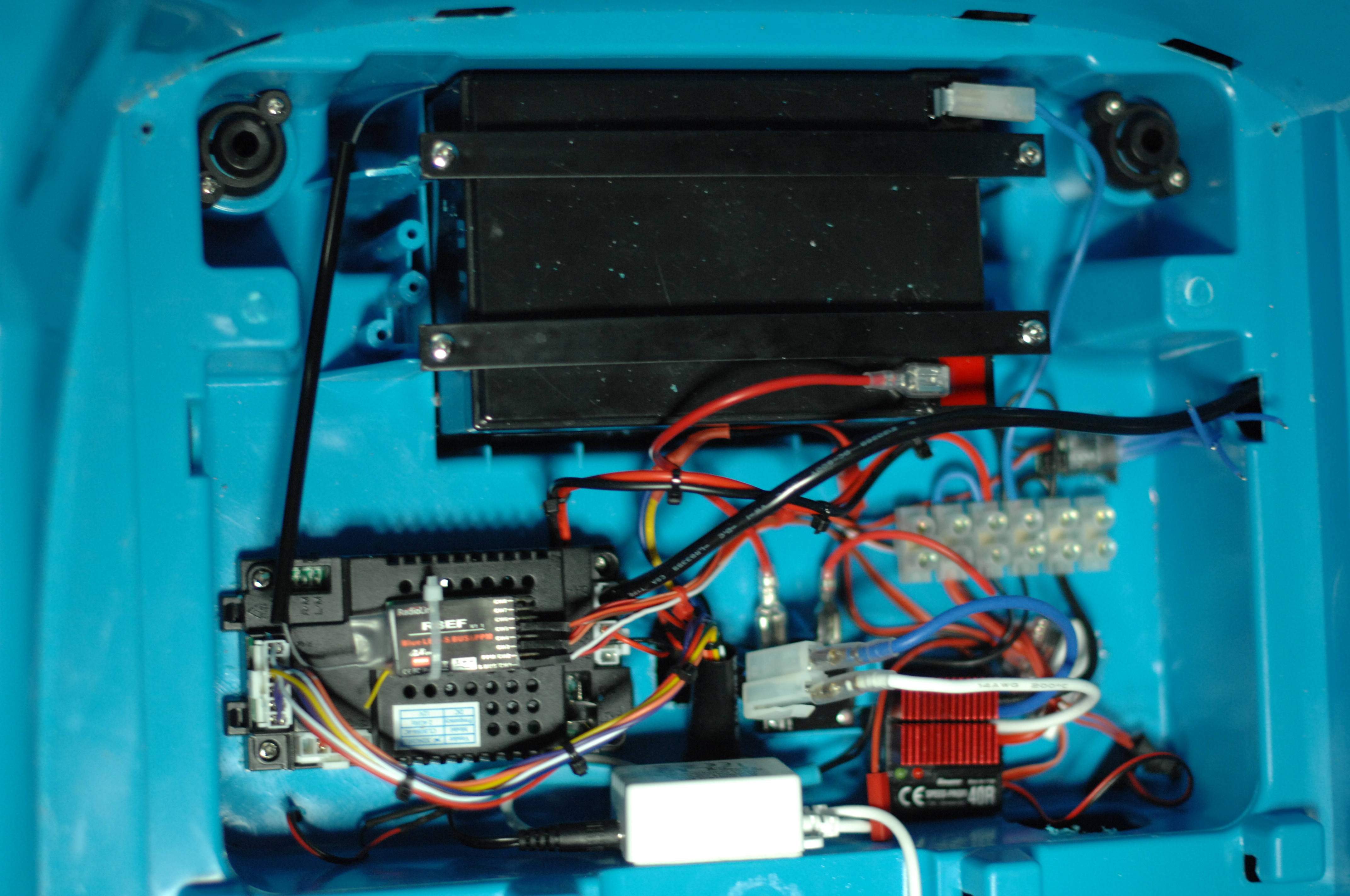
After a bit of tidying up, it is starting to take shape. Doubt it will look like this when i am done, but lets see.
Can you hear me?
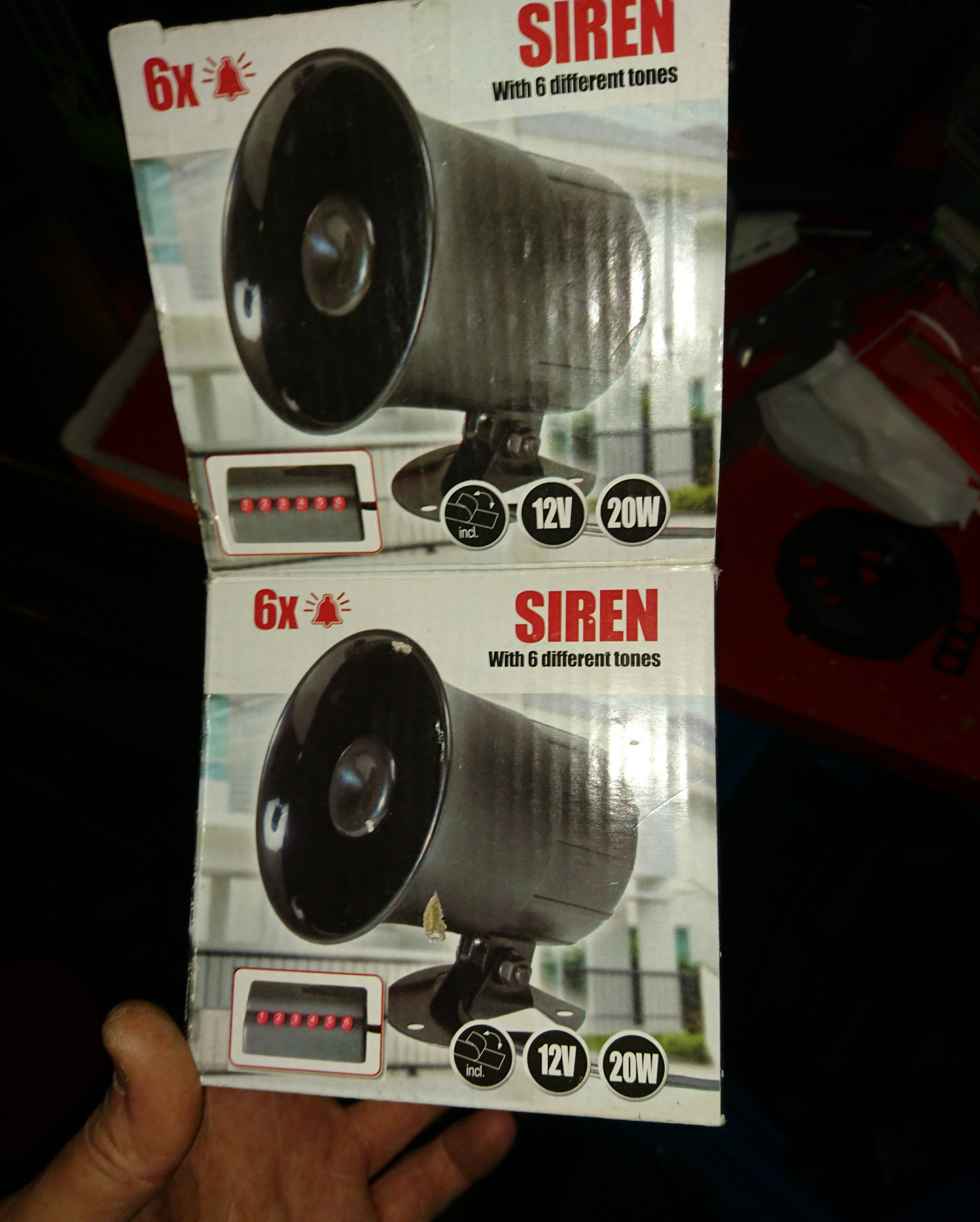
Speaking of sounds needless to say he needs a proper horn. I found this 20 watt siren with 6 tones for less than 10 euros, so that’s going in.
I don’t know how loud it is, but it’s f***ing loud.
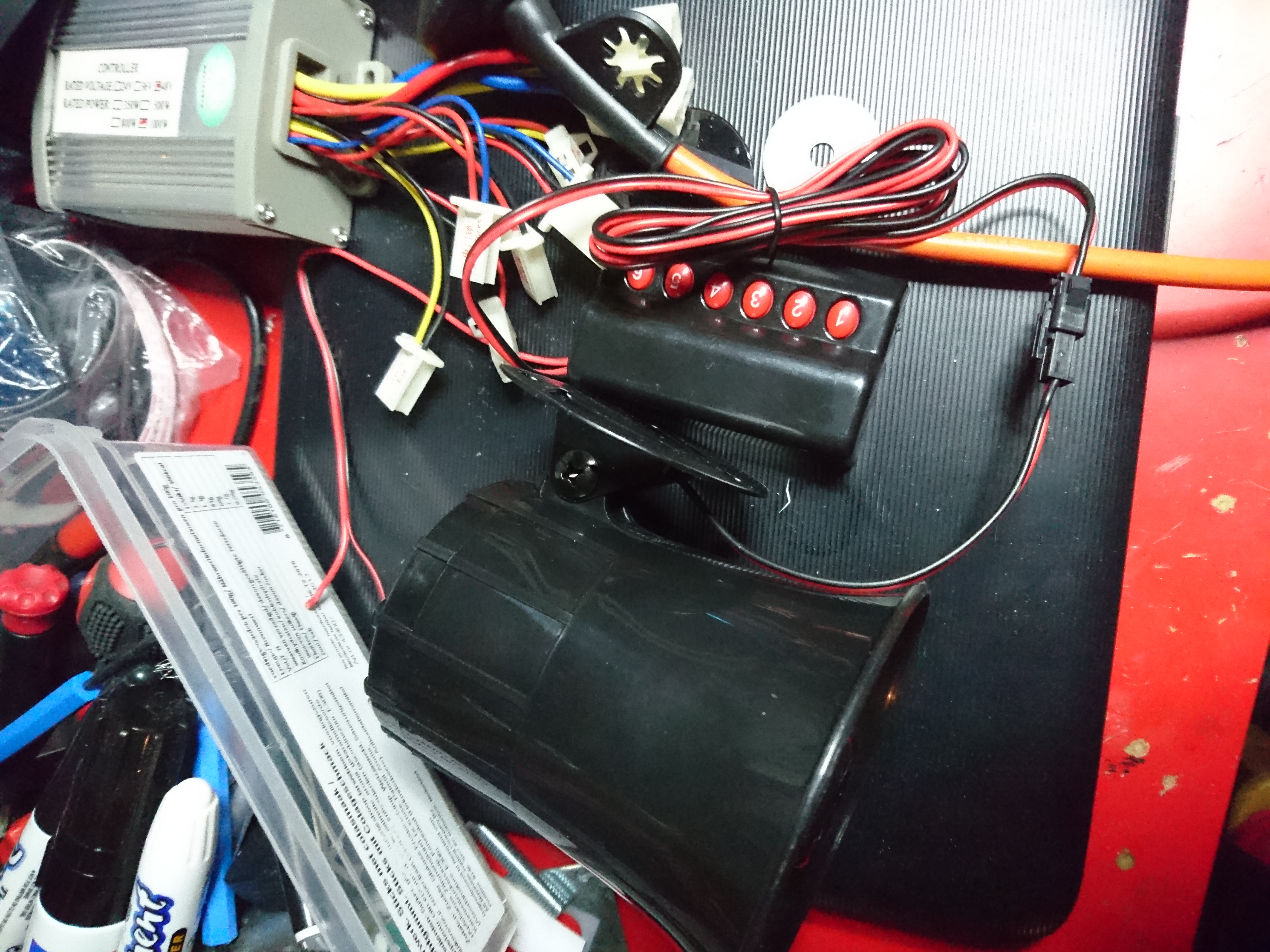
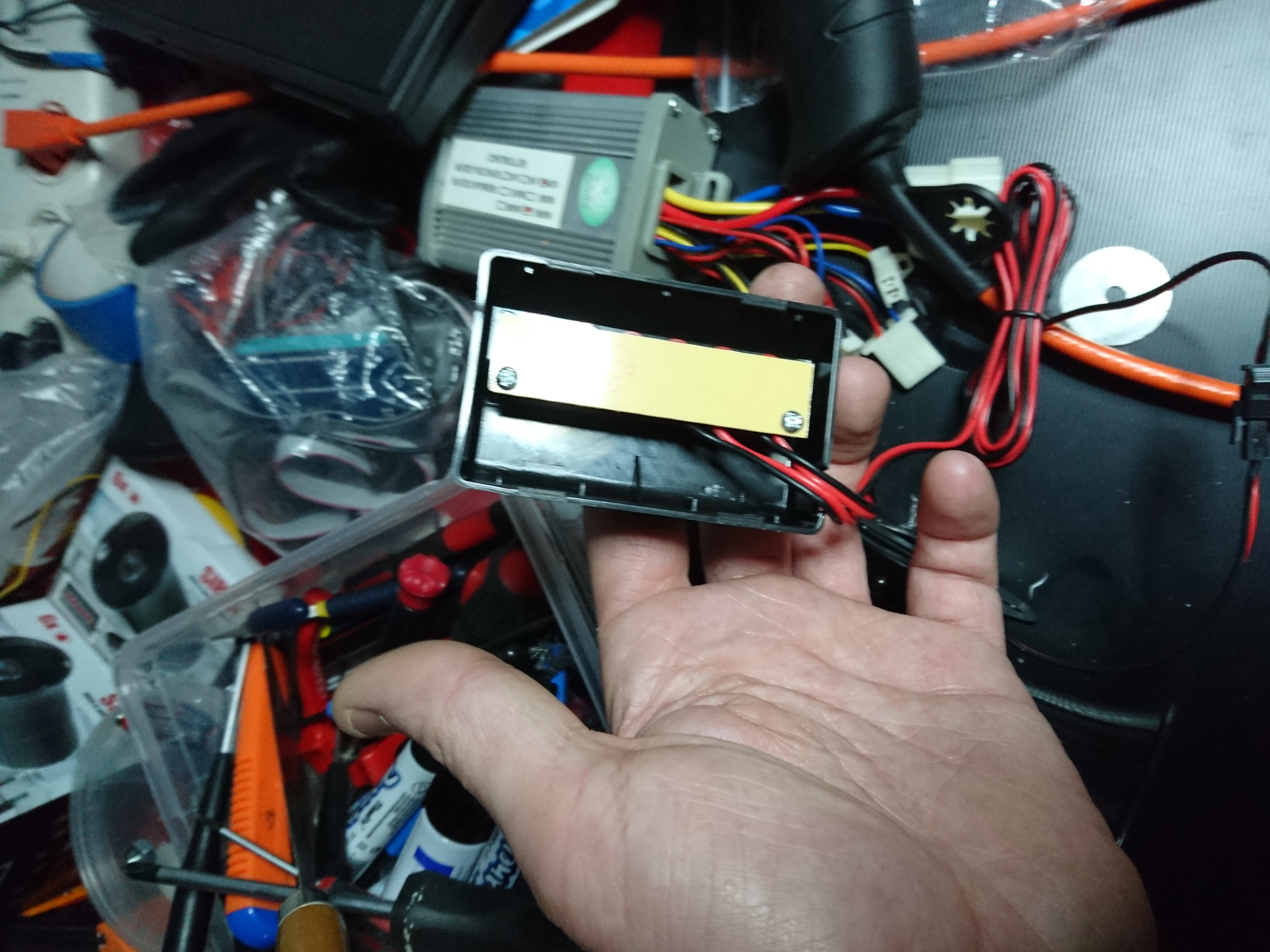
Adding the ugly keypad on the dash would have been a five minute job, but as i mentioned i want a stereo in it at some point and space is of the essence.
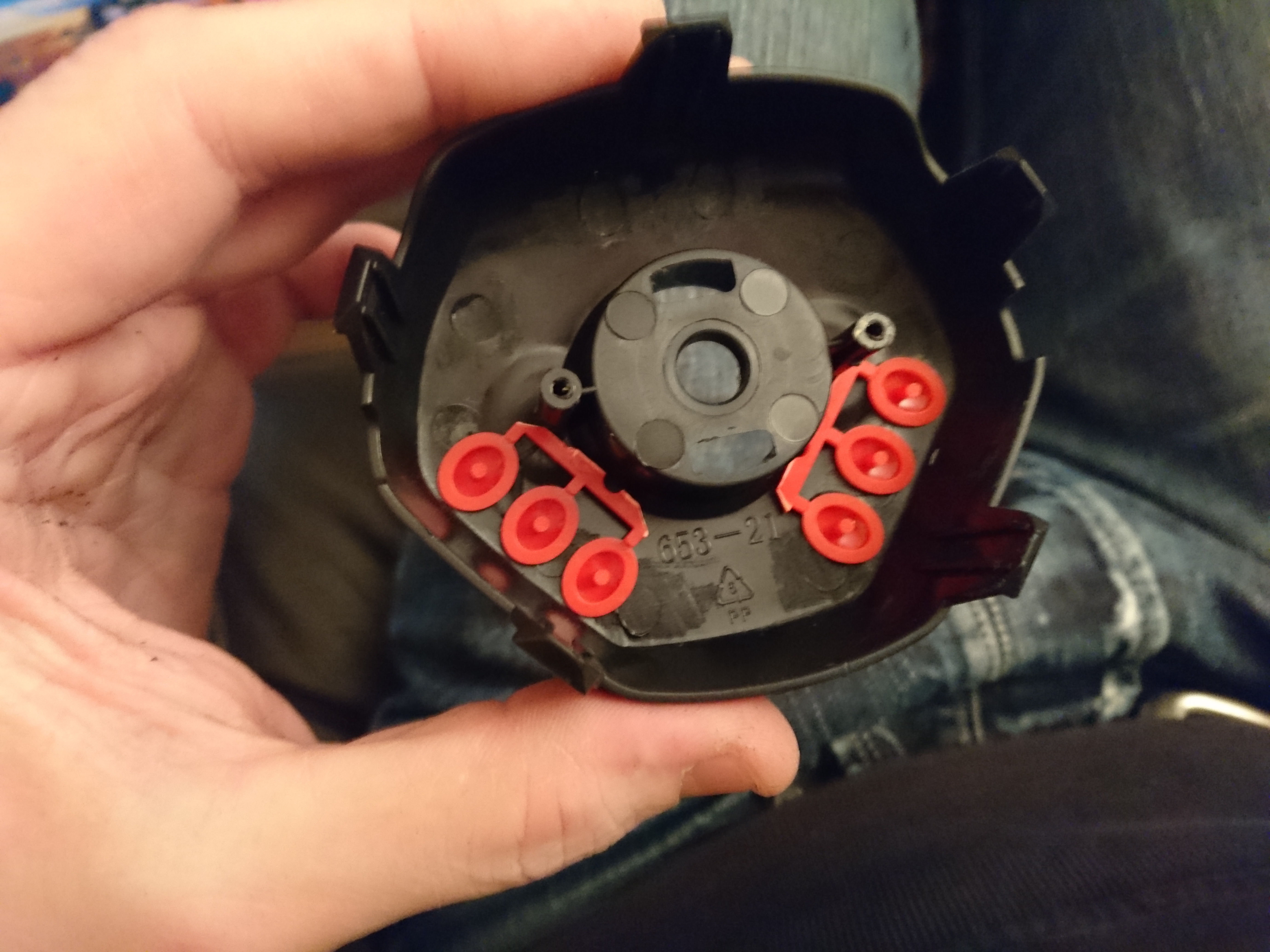
Inside the keypad is a tiny circuit-board that i could make fit inside the steering-wheel, but to fit the center the steering-wheel, it will need to be chopped up.
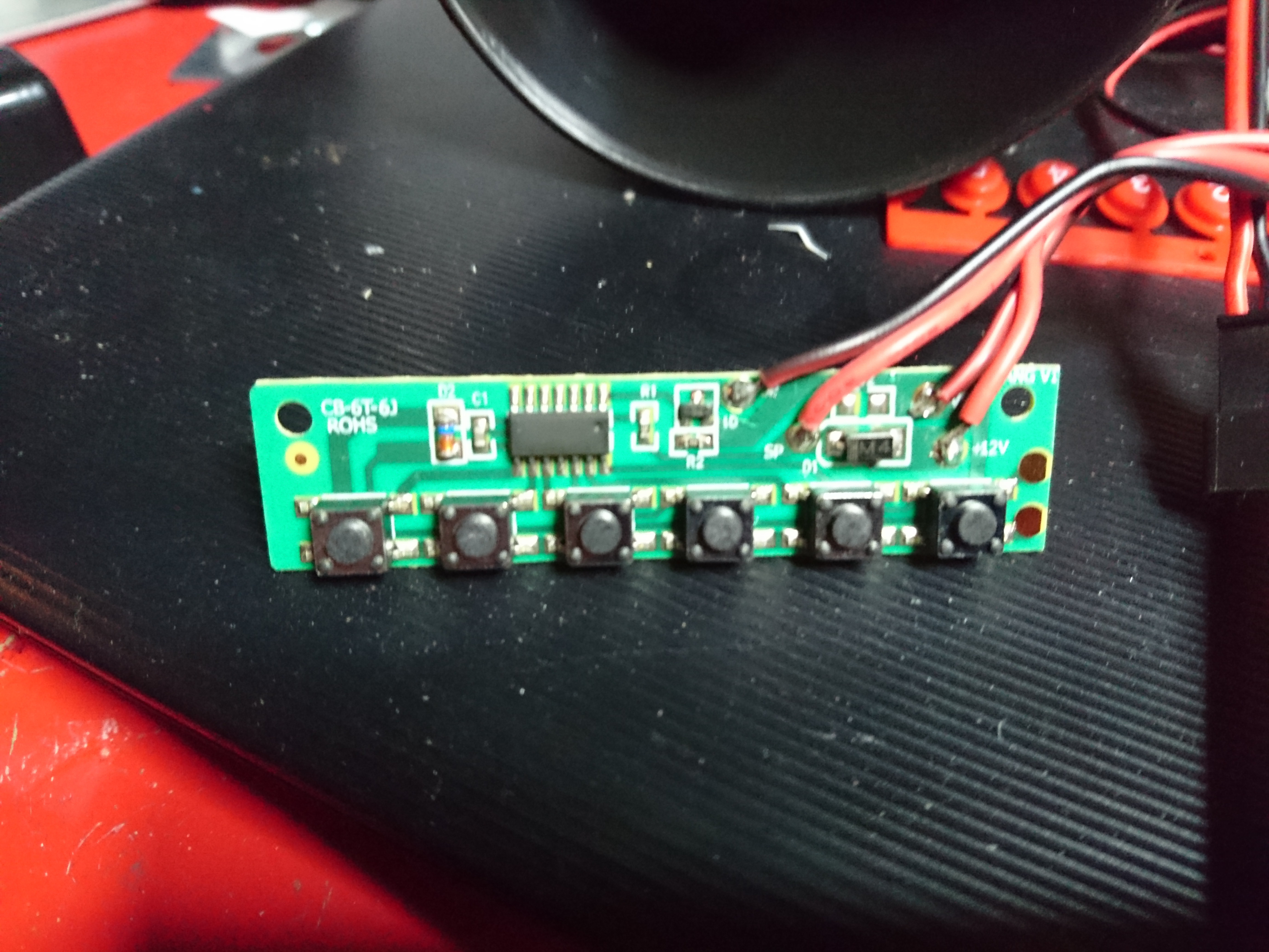
The best part about cheap electronic tends to be single sided circuit-boards which allow you to customize them very simply. I locate the place that has most free space around components.
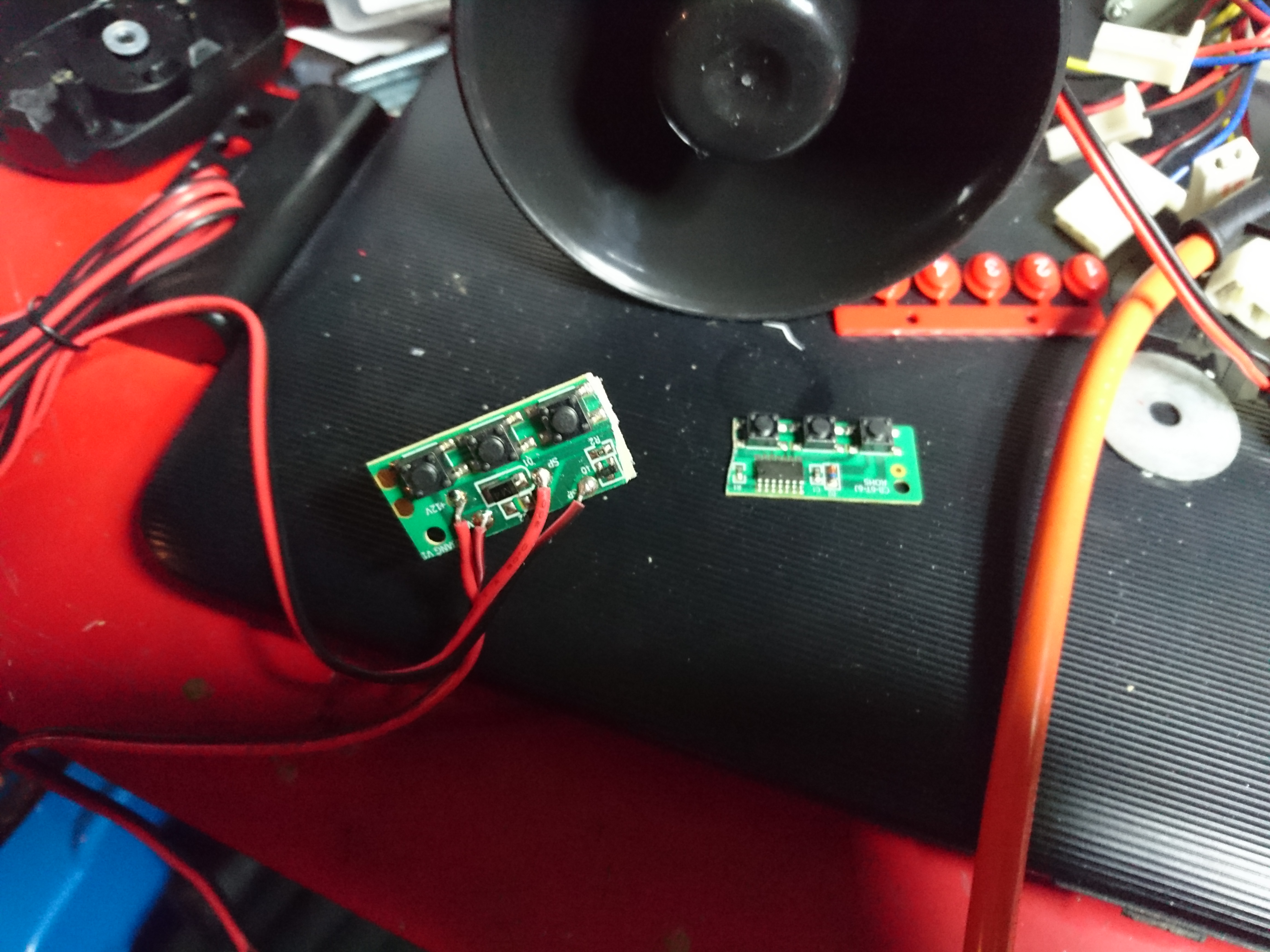
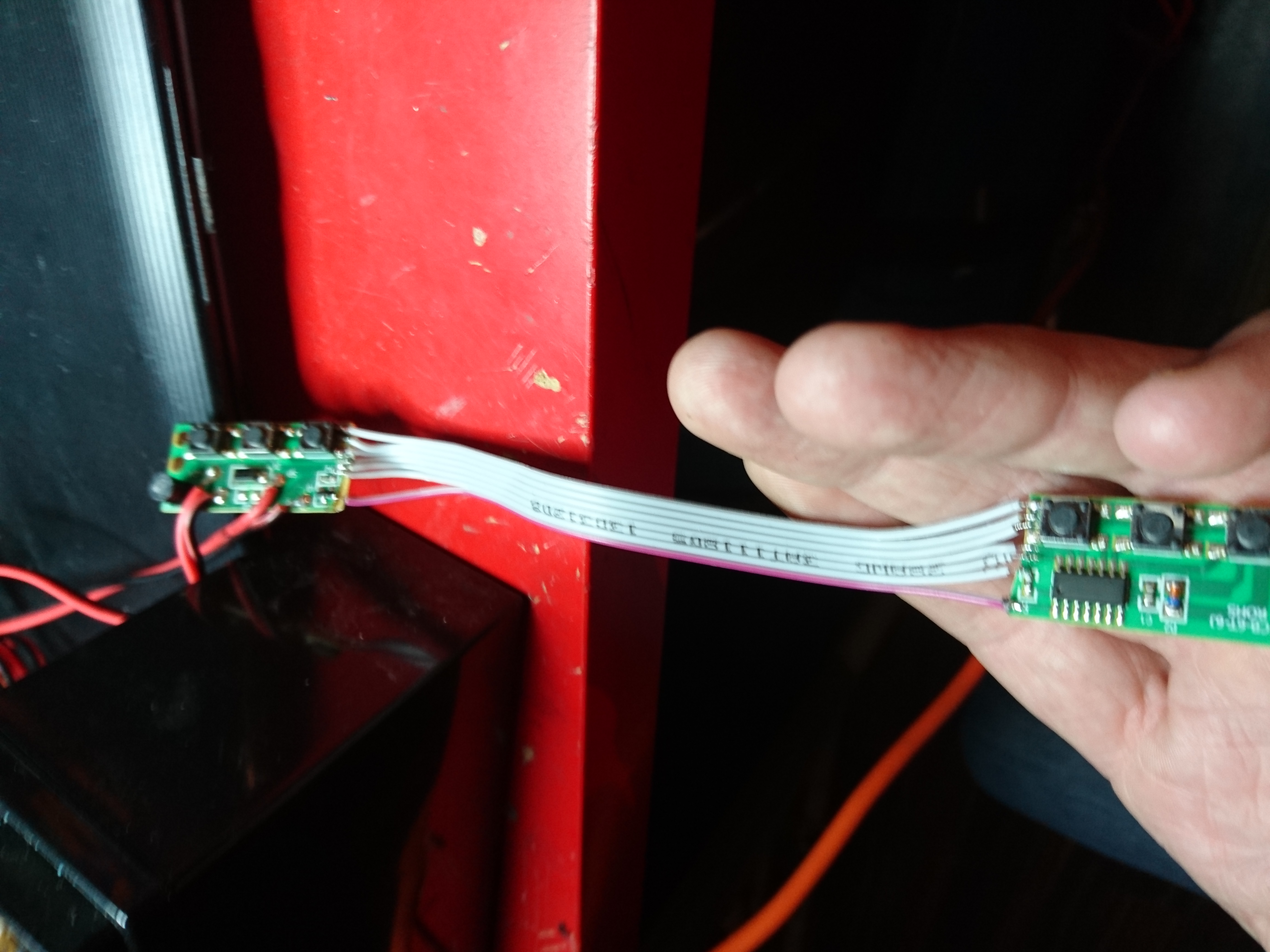
After doing some measurements and make sure it will work i use a hobby-knife to cut it in half, making sure i leave enough copper trace to solder cables on to reconnect the half’s.
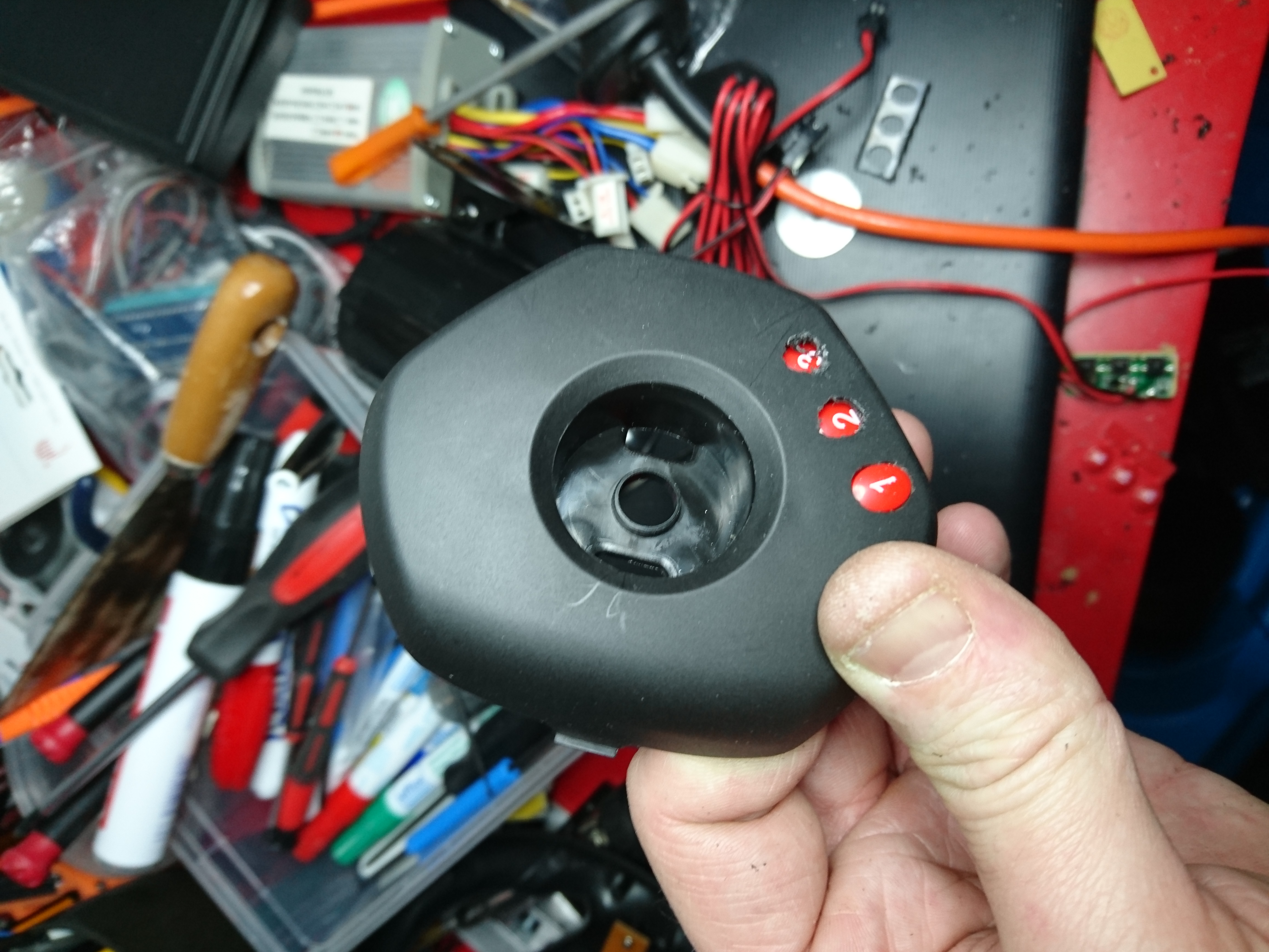
Next i make a few pilot-holes and start the painstaking process of filing away on the plastic. Not scratching it in the process is an art i still don’t master.
The buttons needs to be trimmed down to fit the housing too. Two component glue fixes them in their position and make sure they spring back out again.
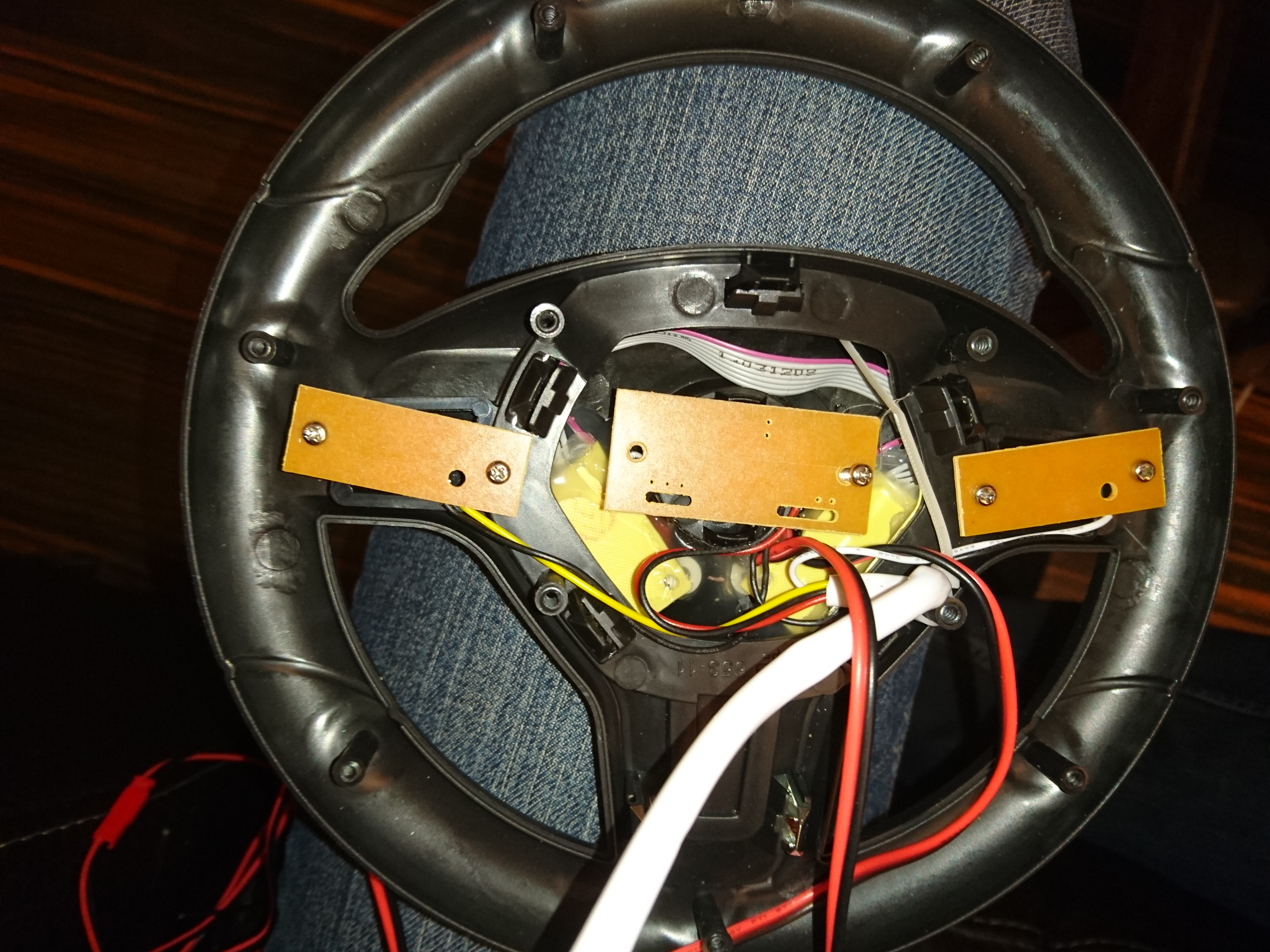
Once everything seems to fall in place i go ahead and solder it. Leaving this part for the end is critical as you are very likely to pull one of these tiny 14 solder-points and the copper it’s attached to if the cable snags later. I secure the ribbon cable with melt-glue to allow me to to be less careful when putting it all together again. The circuit board is screwed back in to new mount-points i took from the old casing, and the whole construction is secured in several layers of melt glue to make sure it can handle hard pushes without breaking of.
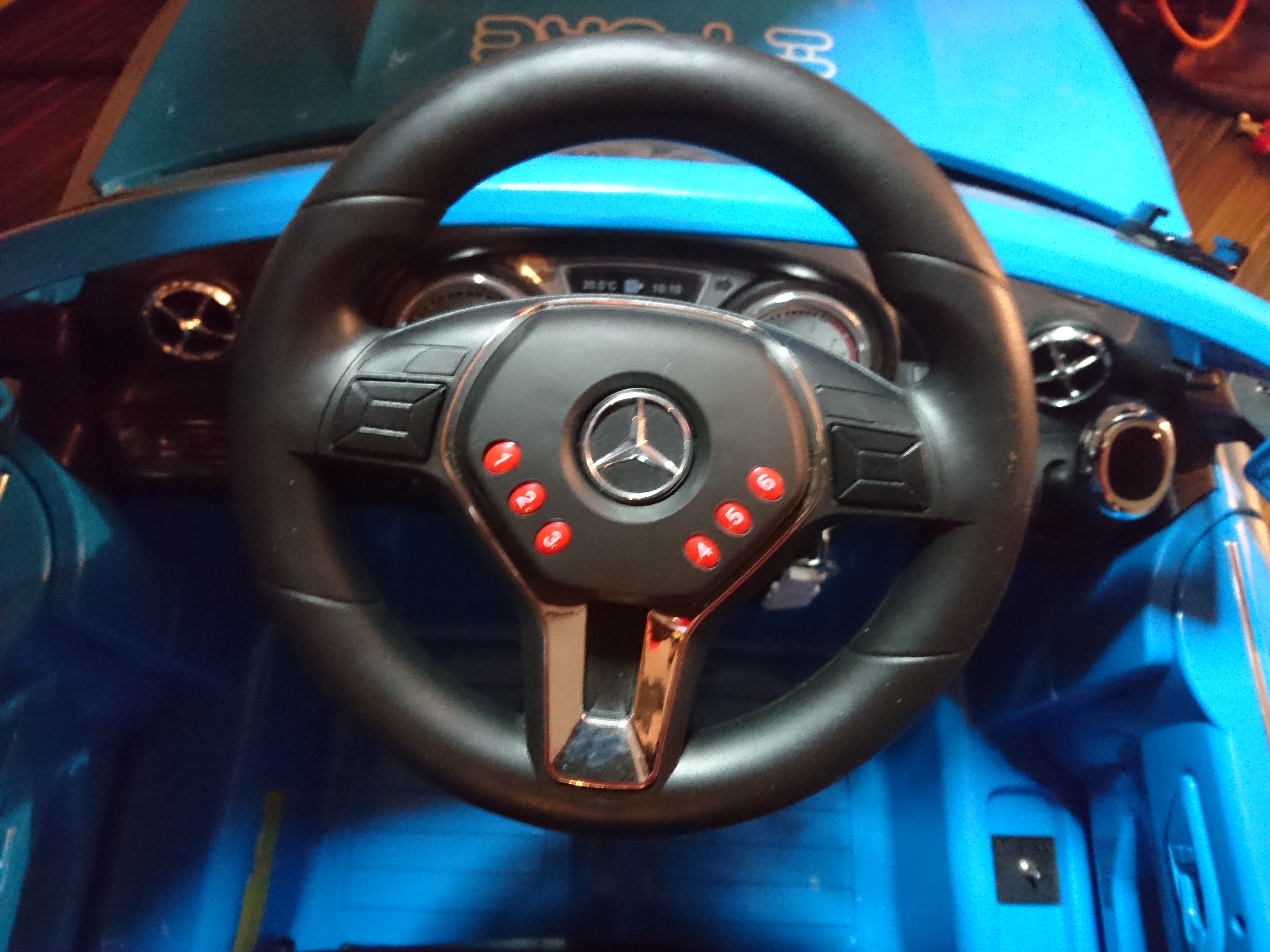
Now all the old electronics is mounted back into the steering-wheel.
Cable is threaded through the steering column, and the wheel is re-attached.
The motors!
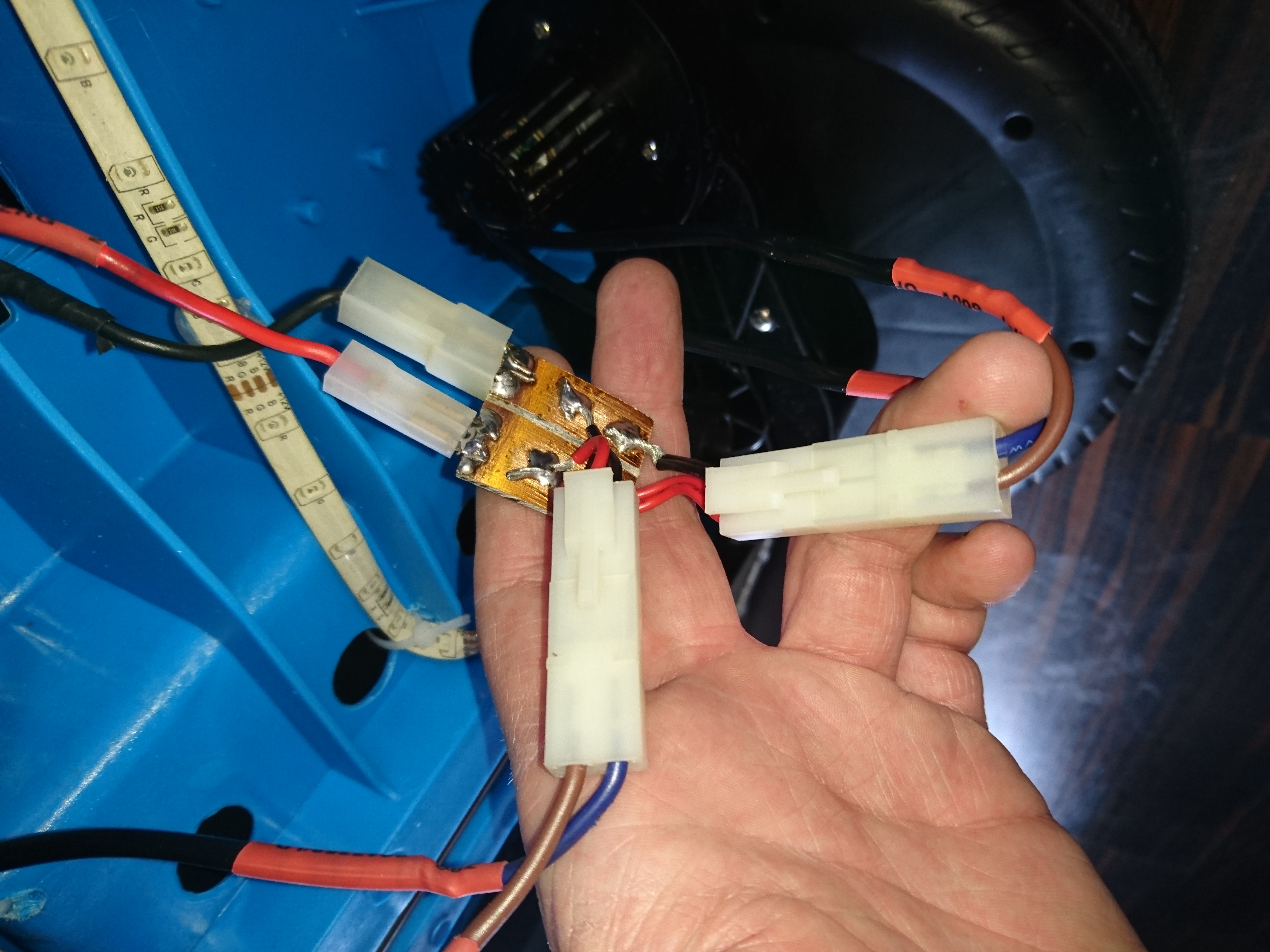
Engines run in a serial connected fashion, but i hear people on the web slapping both one and two extra batteries on these motors, so with the new fat battery i decided i could afford to parallel-connect them instead.
I have two blocks like this. This one parallel connect the engines and the other serial-connects them, if i ever want to return it to that configuration.
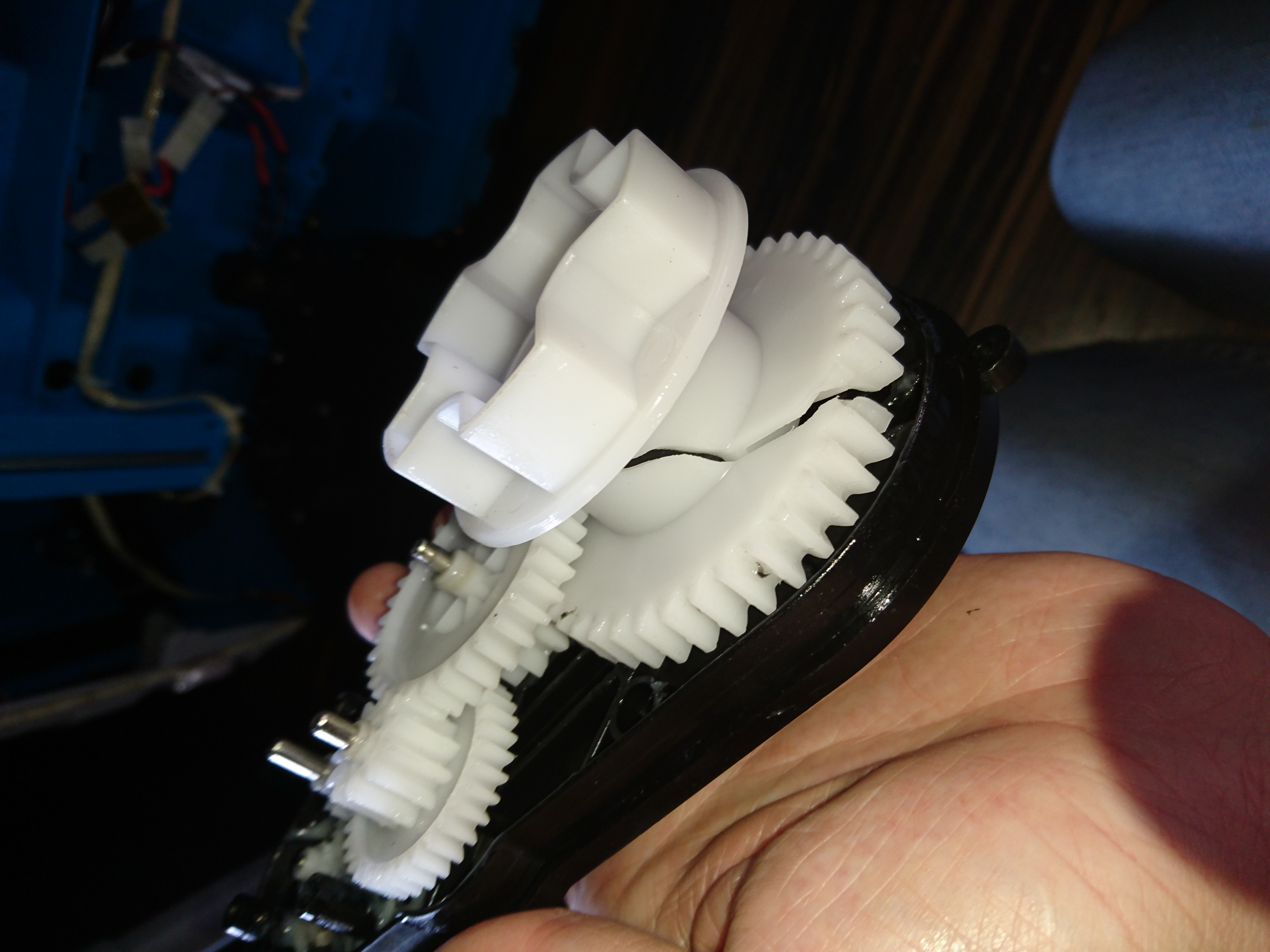
Disaster strikes!
Unfortunately 12 volt, over a 40Amp ESC on a 12ah battery on the RS-390’s was i bit too much for the original design to deal with and one of the gearboxes tossed in the towel.
The accident struck as i was taking it for a test ride on the street by simply reversing the car and hitting full throttle.
I never expected the main cog to crack like this, maybe some of the smaller ones but not the largest..
This made me give up all hope on using those gearboxes for any larger or more powerful type 380/390 motors. I need something a bit beefier for transmission, or it will crumble just like this did very fast.
A new dawn
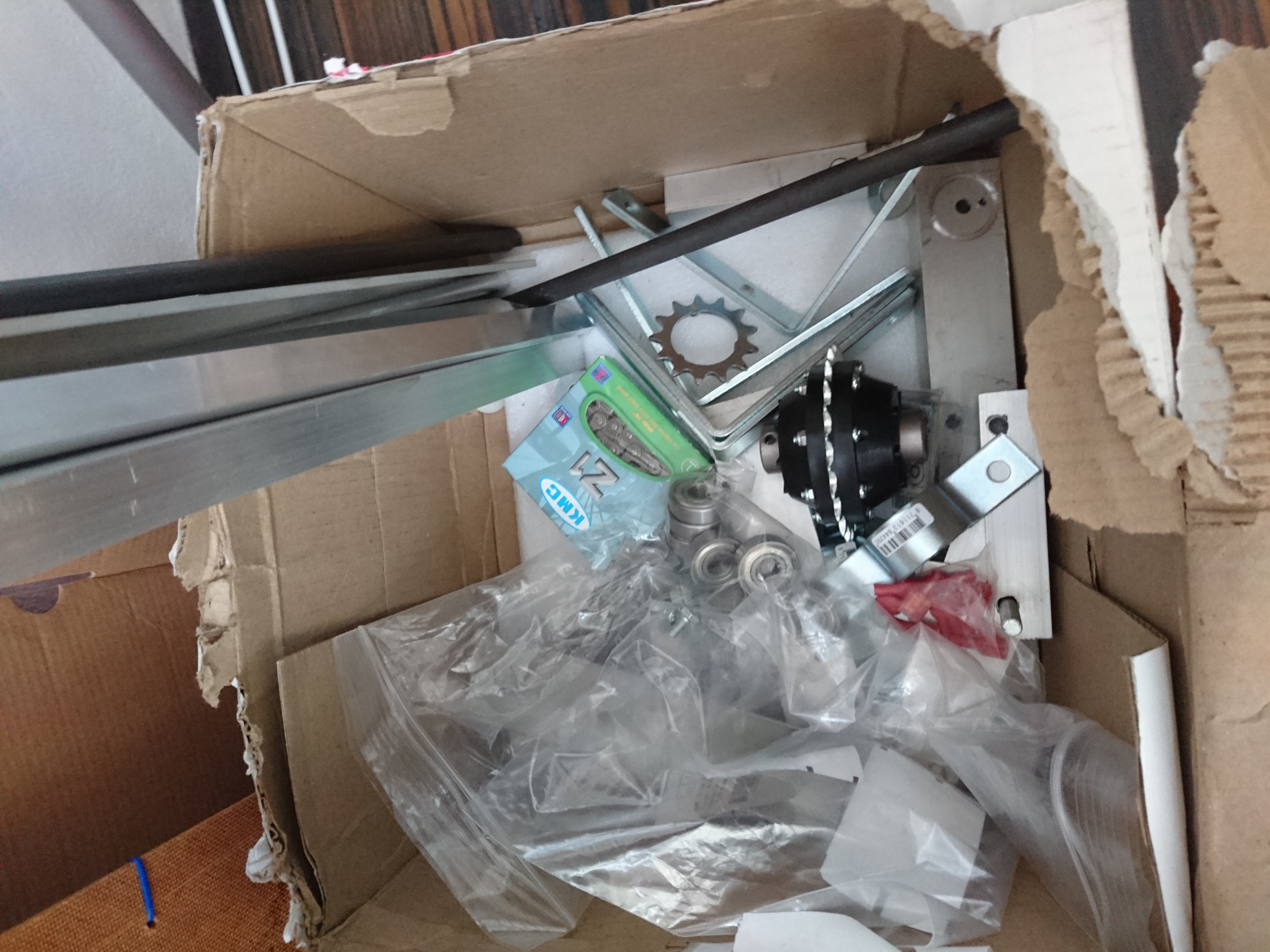
I went above and beyond the original motors when i bought a 48 volt 1000 watt motor of amazon. The motor is meant for a e-scooter and is 200 times stronger than the original engine so a frame will have to be built. I will follow the same practices you would if building a car. If possible with individual suspension and a rear differential to make sure it corners nice. The base will be widened about 100mm and lowered about 30mm to allow it to sit better on the ground.
Material is slowly collected, the engine, cardans and a rear differential has arrived, i am still waiting for the front disk-brakes and 40kg servos.
I also decided this build will need welding. For material i wish i could go aluminum but a lot of people keep advising against it, and my Argon gas is delayed 2 weeks, meaning i might for steel wishbones. I ordered a 200Amp TIG/MMA welding machine which should allow me to weld both stainless and carbon’ed steels. Additionally i had to rebuilt the main fuse-box in my house to be able to run it without burning my house down. As soon as my gas arrives i can start climbing that hill.
In the next part i will get a rear differential, suspension built and the motor mounted.
Suggestions and inspiration is very welcome. Current challenges:
I need wheels and have been looking for weeks with little avail.. They should be 300mm diameter, ~120mm wide, preferably with an aluminium hub and air-filled tires for weight-reduction. Any suggestions are welcome. I currently explored Golfcaddy’s, wheelbarrow, go karts and ATV/Quad.
Suspension. Should be 70mm(compressed)-125mm(decompressed) long and deal with 25kg each.
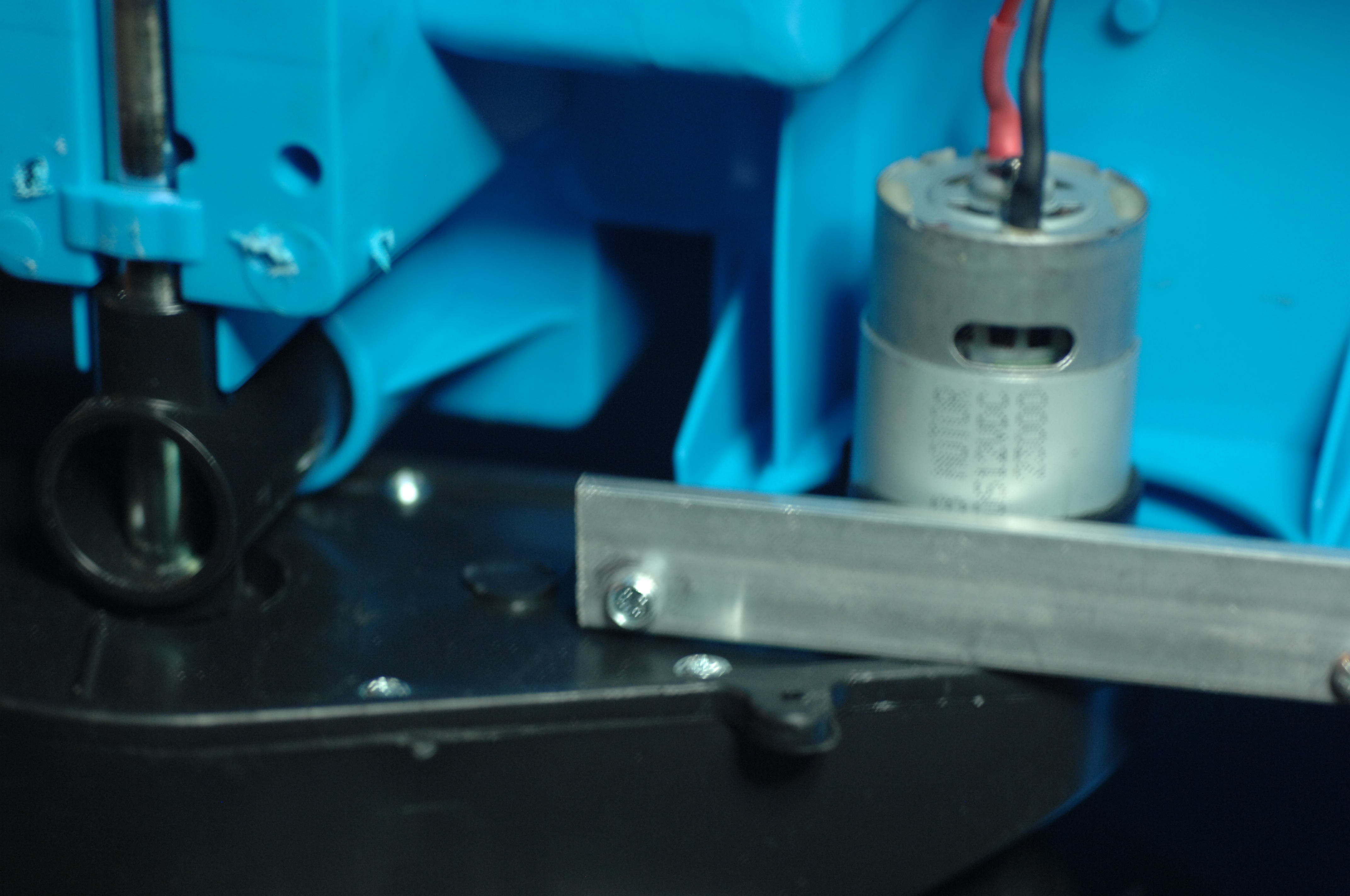 These are the RS-550 12VDC doing 23.000 rpm.
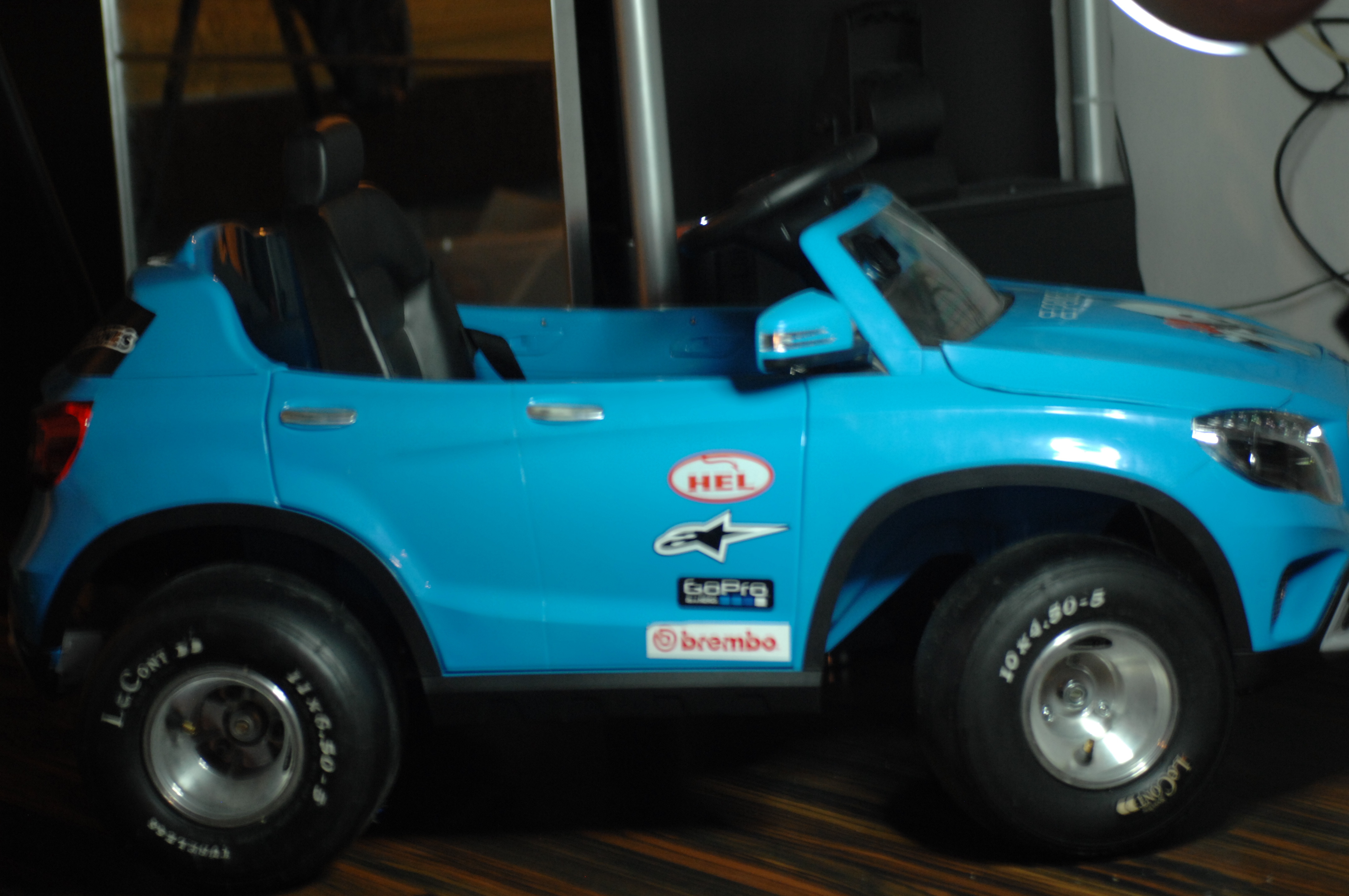
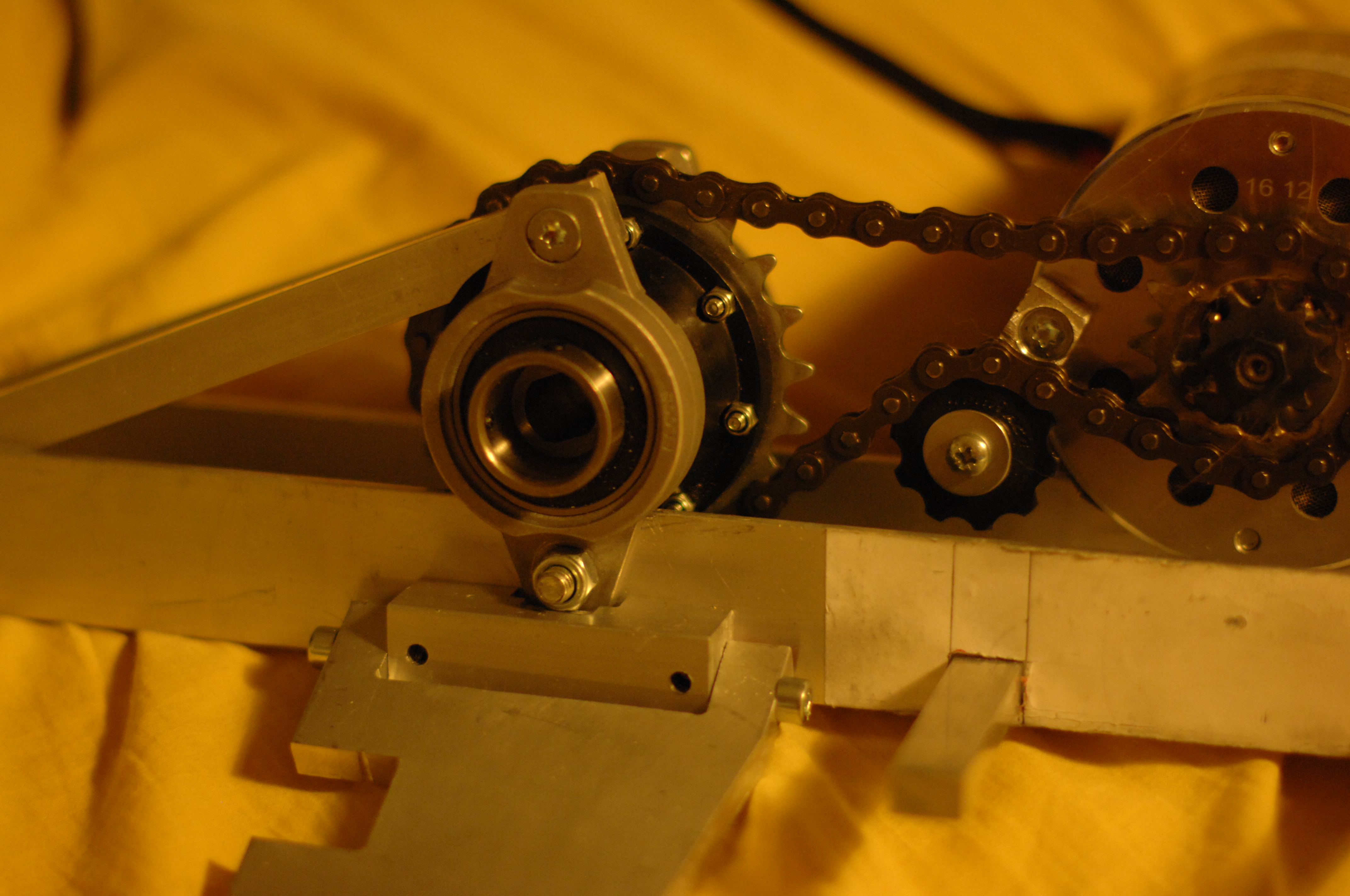 Rear differential, bearings, chain, chain-tentioner, electric motor and the lower control arm mounted. Battery box will be mounted on the opposite side to the motor to balance out the weight.